


3810Plus Installation
2-33980-A2-GB30-40 October 1998
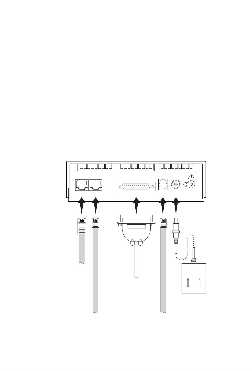
• An 6-pin modular keyed jack for dial (PSTN) lines.
• A 4-pin modular jack for network management
system (NMS) connection.
• A 25-pin DB-25-S receptacle for DTE interface.
Connecting 3810
Plus
Modems with Supplied
Cables
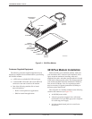
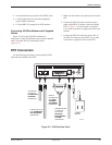
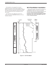
Figure 2-2 shows how 3810Plus modems are
connected to certain TELCO jack types using the supplied
cables. For other TELCO connections, refer to
Appendix D.
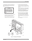
DTE Connection
Use the following procedure to connect the RS-232D
cable from the modem to the DTE:
1. Make sure the modem’s rear panel power switch is
Off.
2. Connect the DB-25-P (male) connector on the
cable to the DB-25-S (female) connector labeled
DTE 1 (Figure 2-2) on the modem’s rear panel.
Use a small screwdriver to tighten the cable to the
modem.
3. Connect the DB-25-P connector on the cable to
the DB-25-S connector on the DTE. Use a small
screwdriver to tighten the cable to the DTE.
495-14677
DB-25-P
CONNECTOR
FOR DATA
TERMINAL
EQUIPMENT
OPERATION
SUB-MINIATURE
4-POSITION
PLUG FOR
NETWORK
MANAGEMENT
SYSTEM
OPERATION
POWER
SUPPLY
6-POSITION PLUG
FOR PERMISSIVE
DIAL NETWORK
OPERATION
8-POSITION
PLUG FOR
LEASED-LINE
NETWORK
OPERATION
OFF
DIAL
LEASED
(3820
Plus
)
LEASED
(3810
Plus
)
DTE 1
NMS
PWR ON
Figure 2-2. 3810
Plus
Rear Panel