


Displaying System Information
7-9
9161-A2-GH30-30
April 1998
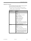
Displaying DSX-1 Channels
Use the Network Channel Display screen to display all of the DS0 assignments
for each DS0 on the DSX-1 interface. This screen also provides information on
the slot assignment for each NAM or APM type.
Use the following menu sequence to display DSX-1 channel information.
Main Menu
→
Status
→
Cross Connect Status
→
DSX-1 Channel Display
Select the desired DSX-1 slot and port.
NOTE:
The DSX-1 Channel screen will not appear if the Interface Status field on the
DSX-1 Interface Option screen is set to Disable.
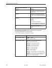
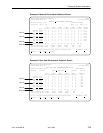
The DSX-1 Channel Display screen displays 24 two-field entries in three rows.
Together, each two-field entry defines the assignment for one DSX-1 interface
time slot. The top field represents the time slot of the DSX-1 Interface. The
bottom field represents the cross-connect status of the associated (top field)
DSX-1 time slot.
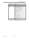
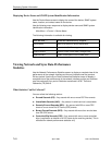
The following information is available for viewing.
The DSX-1 Time Slot Fields (top) . . .
Indicate . . .
D01 to D24 The DSX-1 Interface time slot (01 to 24).
The Cross Connect Status Field
(bottom) . . .
Indicates the . . .
blank Time slot is unassigned.
S
ss
P
p
Voice or sync data port (
p
) of slot (
ss
)
is
assigned to DSX-1 time slot (01 to 24).
Net
nyy
Network Interface
n
(1 or 2), time slot (
yy
)
is assigned to DSX-1 time slot (01 to 24),
using Clear Channel.
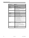
Net
nyy
r Network Interface
n
(1 or 2), time slot (
yy
)
is assigned to DSX-1 time slot (01 to 24),
using Robbed Bit Signaling (r ).
RsvdAPM Time slot is assigned to an APM which is
either:
H failed,
H removed or not installed, or
H has been replaced by an APM type that
is not compatible with the configuration.