


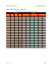
Installing the Model 2160 30
Model 2160 Series User Manual 3 • Hardware installation
Note
When setting up your Model 2160 you must consider cable-length
limitations and potential electromagnetic interference (EMI) as
defined by the applicable local and international regulations. Ensure
that your site is properly prepared before beginning installation.
Location and mounting requirements
The Model 2160 is intended to be placed on a desktop or similar sturdy, flat surface that offers easy access to
the cables. Additionally, you should consider the need to access the unit for future upgrades and maintenance.
This completes the planning phase for installation. The next section begins the installation procedures.
Installing the Model 2160
Unpacking the Model 2160
Inspect the shipping carton for external damage. Note any damage before removing the container contents.
Report any equipment damage to the shipping carrier immediately for claim purposes. Save all packing mate-
rial in case you need to return an item to the factory for servicing.
The Model 2160 comes with the following items:
• Model 2160 Quick Start Guide
• Model 2160
• An RJ-45-to-RJ-45 cable for use with the console and Ethernet ports
• A DB-9-to-RJ-45 (EIA-561) adapter for connecting a PC’s serial port to the Model 2160 console port
Note
Power cables are shipped separately from the Model 2160
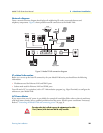
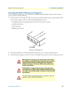
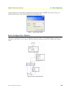
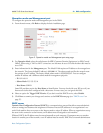
Connecting cables
1. Connect the Ethernet cable to the Management port. Model 2160 supports audi-MDIX switching so you
may use a crossover or straight-through cable.
2. Connect one end of a phone cable to the LINE port and the other end of the cable to a wall jack.
The
Interconnecting
cables must be acceptable for external use
and must be rated for the proper application with respect to volt-
age, current, anticipated temperature, flammability, and
mechanical serviceability.
Do not work on the system or connect or disconnect cables during periods of
lightning activity.
CAUTION
WARNING