


24 of 36
ISSUED: 07-24-12 SHEET #: 180-9023-1
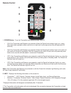
Notes:
1. We recommend that you disconnect and then re-connect the LAN cable to ensure LAN operation. Once
video and audio come back up, the process is complete.
2. To return the units back to WiFi mode press the WiFi Channel 1 button for 5 seconds in front of the
Receiver until all the indicator lights start fl ashing on both the Transmitter and the Receiver. The video
and audio will be lost during this process.
3. LAN setting can be changed to a single unit independently by following the above instruction with only
the Transmitter or Receiver turned on.
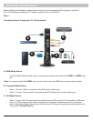
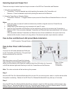
LAN Connection Through Router (LAN One-to-One)
When connecting the HD Flow Pro Wireless Multimedia Kit through a router, the Ethernet IP addresses of
the Transmitter and Receiver need to match the domain of the router (i.e. 192.168.x.x). Once the Ethernet IP
addresses are in the same domain, the indicator lights located at the top of the unit will become solid, signifying
connection.
Confi guring for LAN Through Router (LAN One-to-One)
Note: Networking experience is recommended for confi guring LAN through router settings.
Transmitter and Receiver need to be confi gured to LAN setting individually using the guide below:
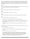
Step 1
Confi gure your computer's Ethernet static IP settings to the following:
IP Address: 192.168.0.157
Subnet Mask: 255.255.255.0
Default Gateway: 192.168.0.1
Step 2
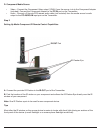
Plug in the HD Flow Pro Wireless Multimedia Kit and ensure it has fully started up (Power/Link Indicator Light
and one Input Indicator light will be blinking).
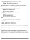
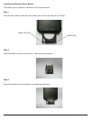
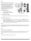
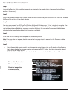
Step 3
Connect one end of the RJ45 cable to the computer and the other end of the RJ45 cable to the Transmitter or
Receiver.
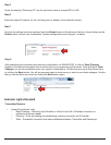
Step 4
Open your preferred browser. In the URL enter 192.168.0.151 for Transmitter, 192.168.0.152 for Receiver and
press enter. You will be taken to the programming page.
Notes:
1. The Transmitter Ethernet IP address is always 192.168.0.151, the IP address of a new Receiver will
always be 192.168.0.152. (Multiple Receivers can be confi gured on a LAN system, each additional
Receiver needs to be assigned an Ethernet IP address one greater than 192.168.0.152. Example
Receiver 1: 192.168.0.152, Receiver 2: 192.168.0.153, Receiver 3: 192.168.0.154, Receiver 4:
192.168.0.155, and so on).
2. Receivers on the same LAN network cannot have identical Ethernet IP addresses.