


46
(2) Assembling the System
The basic procedure for assembling the system is as follows.
1 Assemble the projection install table (RM-V112/RMA-V5010).
2 Mount a one-link mount unit . (40-inch only)
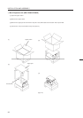
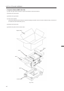
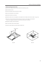
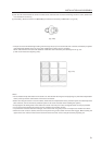
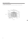
3 Assemble the projection frame (RMF-V4011/V5011). (Refer to Fig. 3-20)
4 Mount the multi-projection unit (RM-V2400N/V2500N).
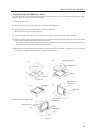
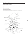
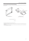
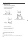
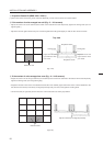
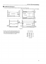
5 Mount the projection screen kit (RMS-V4011/V5011). (Refer to Fig. 3-21, 22)
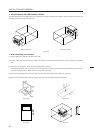
6 Mount the top board , side board , rear panel.
7 Mount the projection unit (RM-V2400N) to the projection cabinet (RMF-V4011R).
INSTALLATION AND ASSEMBLY
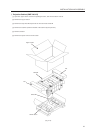
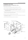
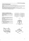
1 Projection Install Tables (RM-V112/RMA-V5010)
Place the installation tables (RM-V112/RMA-V5010) at the specified position and link them together with the bolts and nuts
specified.
First tighten the bolts and nuts temporarily, and after all have been linked, check their height differences and if they are
horizontal before tightening the nuts and bolts firmly.
Do not tighten the adjusters at the legs as their final positions have to be adjusted after assembling all units.
To install at a height greater than the installation table when not using this table, make sure the strength is greater than
required.
The basic procedure for assembling the system for rental-use is as follows.
1 Assemble the projection stand (RM-V112).
2 Mount the 2-link/3-link mount unit (RMA-V2050/V2060).
3 ' Mount the multi-projection unit (RM-V2400N) to the projection cabinet (RMF-V4011R/V4011CR).
4 ' Mount the projection cabinet (RMF-V4011R/V4011CR).
7 ' Mount the projection unit (RM-V2400N) to the projection cabinet (RMF-V4011CR).
The above procedure is recommended. It is explained below.
(Fig. 3-22 50 inch)
Mount the frame on the install table by 4 screws.
(Fig. 3-20 50 inch)
Screen side has
the difference.
Screen side has the difference between the board and frame.
(Fig. 3-21 40 inch)
Difference
Screen side
Rear side