


51
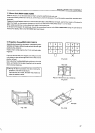
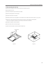
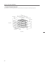
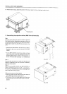
[2] Join the next screen beside the screen mounted as the reference and mount the remaining screens in order. (Stack them
from the bottom to the top.)
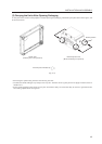
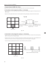
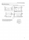
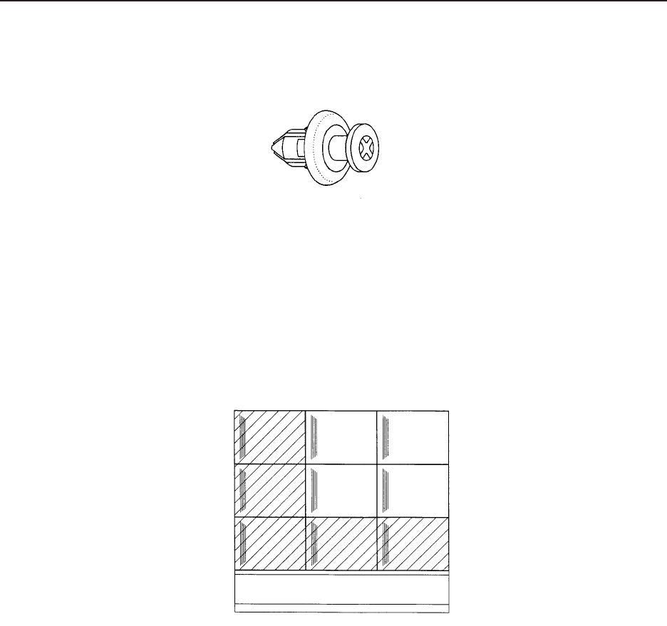
[3] If necessary, attach the screw rivet (BEC1082) provided as the accessory of RMS-V4011. (Fig. 3-36)
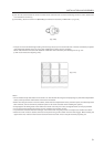
* This part is used to shield the light leaking from the big hole (ø 8) on the outermost side of the left and bottom projection
units (diagonally shaded part in Fig. 3-37) after installing the system. Use it if necessary.
Screen units with this rivet cannot be attached outside the area indicated by the standing lines in fig. 3-37.
(It will not connect to the adjoining units.)
(Fig. 3-36)
(Fig. 3-37)
<Note>
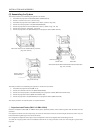
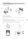
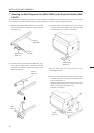
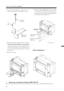
• Do not mistake the top and bottom of the screen unit. The side with the longer screw projecting out (side with transportation
screw) is the top and the side with the 8 mm hole is the bottom.
• Before mounting the screen unit to the cabinet, check that the transportation screw, protection panel, and black tape have
been removed. (Do not remove the protection panel on the outer-most side when installing the system.)
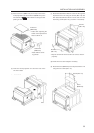
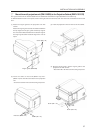
• Always tighten the linking bolts of the cabinet and screen unit with your hands, and tighten them as firmly as possible.
• Put on gloves when stacking the screen units for protection and perform in twos.
• To prevent the lenticular sheet from damage, mount the screen unit gently and do not subject it to vibration and shock.
• When the screen units are stacked, the head of the panel fixing screws and 8 mm holes will engage. When stacking the
upper screen unit, make sure that it does not brush the lower screen unit as it has panel screws projecting out.
INSTALLATION AND ASSEMBLY