


56
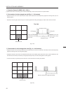
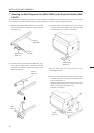
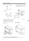
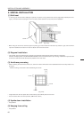
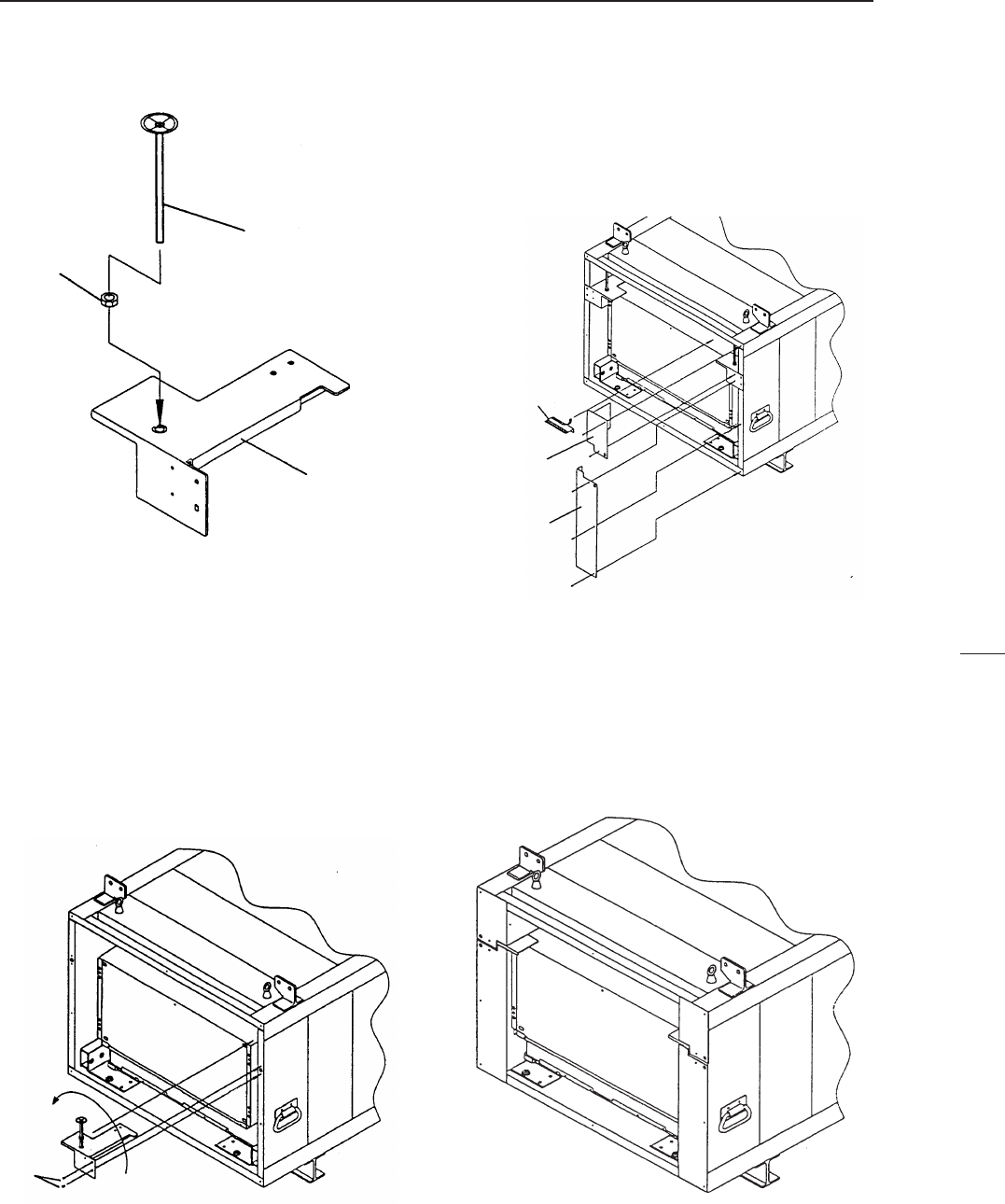
(10) Attach the adjuster (BEF1011) attached with a nut
(M8) to the rear holders R and L (BNG1205, 1206).
(
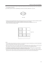
12
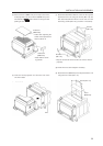
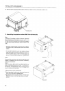
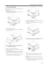
) Attach each rear panel (BMR1069, 1070, 1071, 1072) to
the unit and the rear holders R and L using the screws
(3 × 8). Furthermore, to cover up the gap at the top of
the projection unit, paste the hinder panel (BMR1075)
over the top board and projection unit.
[After Completion]
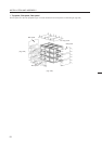
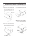
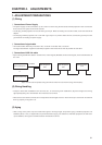
INSTALLATION AND ASSEMBLY
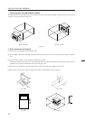
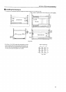
4' Mounting the Projection Cabinet (RMF-V4011R)
Projection cabinet can mount to use the conventional method. For details, refer to the RM-V2000A technical manual.
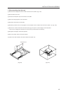
(
11
) While tilting the parts assembled at step 10, insert it
into the holes on the shoulder of the multi-projection
unit and attach with the screws (3 × 12). (2 screws × 2
locations). Furthermore, pull up the adjuster to the top
of the unit while rotating it, and pull down the nut to
the rear holders R and L while rotating it to secure the
projection unit.
* Tighten the nuts tightly.
Adjuster
(BEF1011)
nut
(M8)
Hinder panel
(BMR1075)
Rear panel L (upper)
(BMR1070)
Rear panel L (lower)
(BMR1072)
screws
(M3 × 12)
Screw : M3 × 8
Rear holder L
(BNG1205)