


54
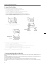
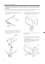
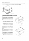
3' Attaching the Multi Projection Unit (RM-V2400N) to the Projection Cabinet (RMF-
V4011R)
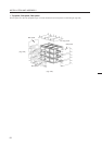
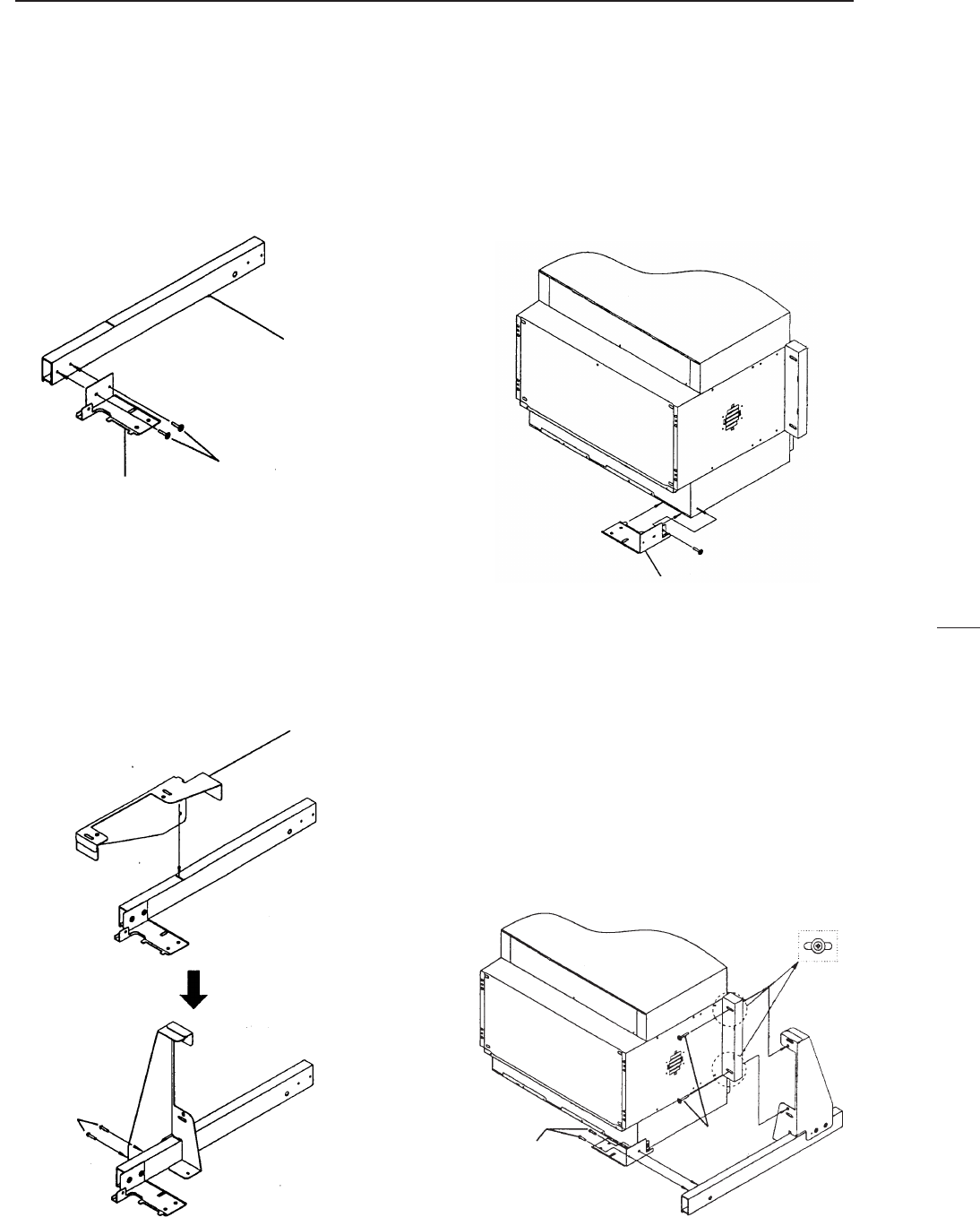
The figure shows the assembling procedure of the left attachment. Assemble the right attachment in the same way. The parts
on the right side of the screen are R and those on the left side are L from the view point against the screen.
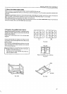
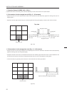
(1) Attach the attachments R and L (BNG1173, 1174) to the
front of frames R and L (BNG1207, 1208) using the
screw (M5 ×15).
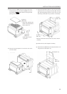
(2) Insert the claws of holders R and L (BNG1150, 1151)
into the slits of frames R and L, rotate them as shown
in the figure, and attach using the screws (M5 × 15). (2
pieces × 2 locations).
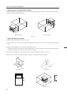
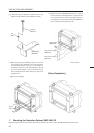
(3) Insert the claws of the attachments R and L into the
rear slits of the multi-projection unit, and attach using
the screws (M5 × 15). (1 piece × 2 locations).
INSTALLATION AND ASSEMBLY
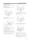
Frame L
(BNG1208)
Screw
(M5 ×15)
Attachment L
(BNG1174)
Holder L
(BNG1151)
Screw
(M5 × 15)
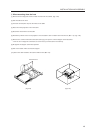
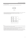
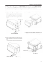
(4) Attach the parts assembled at steps (1) and (2) onto
the multi-projection unit. Attach the attachments R
and L to frames R and L.
Using the screw (M5 × 15) as shown in the figure, and
attach the attachments R and L to the rear of the pro-
jection unit using the screws (M5 × 50).
(2 screws × 2 locations).
*Drop the screw-lock fluid to screws so as not to
loosen.(Right and left)
Attachment L
(BNG1174)
Screw
(M5 × 50)
Screw
(M5 × 15)