Removal and replacement procedures 35
4.
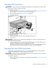
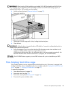
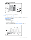
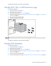
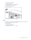
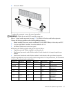
Remove the DIMM.
To replace the component, reverse the removal procedure.
IMPORTANT: DIMMs do not seat fully if turned the wrong way.
Refer to "System board components (on page 51)" for DIMM slot locations and bank assignments.
Observe the following guidelines when installing additional memory:
• DIMMs installed in the server must be unbuffered PC2-4200 DDR2 DRAM, 64 bits wide, and ECC.
• If only a single DIMM is installed, it must be installed in slot 1A.
• All DIMMs installed must be the same speed.
BIOS detects the DIMM population and sets the system as follows:
• Single-channel mode: DIMMs installed in one channel only
• Dual-channel asymmetric mode: DIMMs installed in both channels but of unequal capacities per
channel
• Dual-channel interleaved mode: DIMMs installed in both channels with equal channel capacities
The following table lists some, but not all, possible configurations. For best performance, HP recommends
dual-channel interleaved mode configurations.
Channel A Channel A Channel B Channel B Total memory Mode
Slot 1 Slot 2 Slot 3 Slot 4
512 MB — — — 512 MB Single-channel
512 MB — 512 MB — 1 GB
Dual-channel
interleaved
1 GB — — — 1 GB Single-channel
1 GB — 1 GB — 2 GB
Dual-channel
interleaved
1 GB 1 GB 1 GB — 3 GB
Dual-channel
asymmetric
1 GB 1 GB 1 GB 1 GB 4 GB
Dual-channel
interleaved


