


220
PRO-610HD, PRO-510HD, SD-582HD5, SD-532HD5
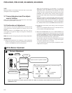
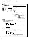
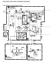
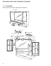
1. P.D. (1)
Failure in the POWER SUPPLY Assy and the AUDIO Assy.
There are four main possibilities:
1. Abnormality in the regulator of the heater
2. Blown fuse(s) in secondary
3. Abnormality in RELAY (RY102)
4. Abnormality in AUDIO OUTPUT
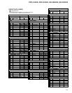
Status Causes Check Items Probable Defective Parts
D223
ANODE Hi
Abnormality in the regulator for
the heater
The voltage of HT- at TP205 is NOT approx. 19 V, and
that of the HT+ at TP204 is NOT approx. 26 V.
Q201, R202, D210, D209
D207
ANODE Hi
Blown fuse(s)
The voltage HT+ (approx. 26 V) at TP204 is NOT
supplied.
CONV. AMP Assy and
DEFLECTION SERVICE Assy
The voltage (approx. 35 V) at TP203 is NOT supplied. AUDIO Assy
The voltage (approx. 11 V) at TP209 is NOT supplied. VIDEO Assy
D911
ANODE Hi
Abnormality in RELAY
The RELAY signal is NOT high (ON) at TP904. SIGNAL Assy
P.D. even if the RELAY signal is high (ON) at TP904. Q904, Q905 RY102, R102
D203
ANODE Hi
Abnormality in AUDIO OUTPUT
The SP line (CN5611) is disconnected. Connect the SP line.
The voltage at the negative electrode of the C5616 and
C5617 is 5.2 V or more.
C5616, C5617 (VIDEO Assy)
Note: The anode of the diode is high only for a short time after the power is turned on until the protection circuits are activated (P.D.) The
LEDs are lit by the HOLD circuit.
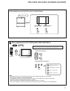
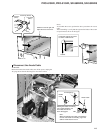
In a case when the power cannot be on with no LED lit, check the following:
1. Check if the FU101 fuse in the POWER SUPPLY Assy is blown.
2. Disconnect and check connector E1 (CN201) to see whether STB 5 V is supplied.
If STB 5 V is supplied, replace the SIGNAL Assy. If STB 5 V is NOT supplied, replace the POWER SUPPLY Assy.
3. Disconnect and check connector E1 (CN201) to see whether AC CLK is supplied.
If AC CLK is supplied, replace the SIGNAL Assy. If AC CLK is NOT supplied, replace the POWER SUPPLY Assy.
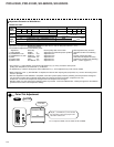
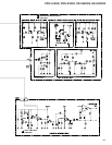
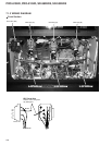
2. P.D. (2)
Failure in the DEFLECTION SERVICE Assy.
There are four main possibilities:
1. H. deflection overload detection (1)
2. H. deflection stopping detection
3. H. deflection overload detection (2)
4. X-ray protection
Status Causes Check Items Probable Defective Parts
D312
ANODE Hi
Overload detection 1
Q309, Q324 (short-circuited between
C and E)
D309
ANODE Hi
Stopping H. deflection
Is the connector of the deflection yoke plugged in? Plug in the connector.
No H. OSC signal at TP304 (F=31.5 kHz, Duty 50%) IC301, Q309
No DH. BLK signal at TP305 Q309
D615
ANODE Hi
Overload detection 2
Q612, Q613 (short-circuited between
C and E)
About one minute after the power is turned off, disconnect
the K4 connector and turn on the power. Then the power is
not turned off (no P.D.).
IC5101, IC5151 and IC5201 in the
CRT DRIVE Assy
D621
ANODE Hi
X-ray protection
No change in the ABL voltage (no DC change) at Pin 12 of
the CN305 when a 100%-white signal is repeatedly
connected and disconnected
D2224 (short-circuited)of the SUB
VIDEO Assy
T601 (FBT) rare short