195
PRO-610HD, PRO-510HD, SD-582HD5, SD-532HD5
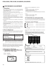
6.1 INTRODUCTION
• IMPORTANT
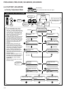
When replacement of the following assemblies are required during repairs, be sure to replace the EEPROMs with the mounted ones in order to
retain the adjustment data of the unit and to facilitate adjustment after the replacement of the assemblies.
Notes:
• Even if the EEPROMs are replaced, adjustment may be necessary, depending on the part or assembly to be replaced.
For details, see page 197.
• Even if the EEPROMs are replaced, if the EEPROMs are damaged or if their data have been changed from the adjustment data, the status
before the failure will not be restored. Check the status of the unit after replacement of the EEPROMs, and readjust if necessary.
6. ADJUSTMENT
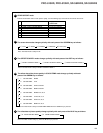
Name of Assy EEPROM Main Contents of Memory
SIGNAL Assy IC2454 [24LC32(I)P] Adjustment data, such as W/B and color data, in FACTORY mode
User data set on the MENU
DIGITAL CONV. Assy IC1410 [24LC128P] Convergence adjustment data
IC1656 [24LC08B(I)P] Convergence offset data
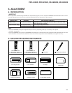
Remote control unit
AXD1448 (CU-SD110)
(For PRO-610HD, PRO-510HD)
Remote control unit
AXD1449 (CU-SD111)
(For SD-582HD5, SD-532HD5)
Monoscope
For HD Signal generator
Screwdriver
Adjustment screwdriver
Dual-trace oscilloscope
Frequency counter
Color bar generator
D. DC Voltmeter
LD Player
6.2 JIGS AND MEASURING INSTRUMENTS


