


221
PRO-610HD, PRO-510HD, SD-582HD5, SD-532HD5
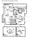
3. P.D. (3)
Failure in the CONV. AMP Assy
The following reason may be suspected:
1. V. deflection stopping detection
Status Causes Check Items Probable Defective Parts
D923, P.D.
LED, lit
V. deflection stopping
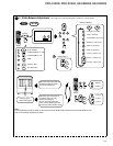
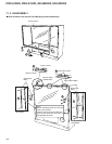
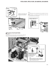
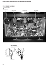
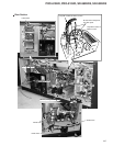
Check that the connectors (G1, G2, G3) of the
convergence yoke are plugged in.
Plug in the connectors.
Check that the connectors (G4, G5) of the DIGITAL
CONV. Assy are plugged in.
Plug in the connectors.
Check that the connector (H4) from the POWER
SUPPLY Assy is plugged in to the DIGITAL CONV.
Assy.
Plug in the connectors.
Check that the connector (H3) from the
DEFLECTION SERVICE Assy is plugged in to the
DIGITAL CONV. Assy.
Plug in the connectors.
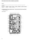
Abnormality in V. BLK 2 waveform that is output
from Pin 6 of the CN1653 in the DIGITAL CONV.
Assy (too long a high period with the DC voltage on)
IC4802 in the SUB VIDEO Assy
Abnormality in V. BLK 0 waveform that is output
from Pin 2 of the CN1652 in the DIGITAL CONV.
Assy (too long a high period with the DC voltage on)
IC301 in the DEFLECTION SERVICE
Assy
No waveform is output from Pin 1 of the CN902. Q913, Q914
Note: The anode of the diode is high only for a short time after the power is turned on until the protection circuits are activated (P.D.) The
LEDs are lit by the HOLD circuit.
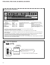
Be sure to check the fuses in the POWER SUPPLY Assy because one or more may be blown as a result of short-circuiting of the load circuit of
the CONV. AMP Assy. See the table below.
Note that the power may be shut down when the voltages 25 V, -20 V, +5 V and -5 V from the POWER SUPPLY Assy are not supplied because
the CONV. AMP and DIGITAL CONVER. Assys are powered by the POWER SUPPLY Assy.
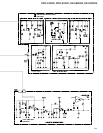
If the FU202 and FU204 fuses are blown, see the following table:
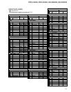
Causes Check Items Probable Defective Parts
Too high loading on the CONVER. AMP
Check that waveform signals are output from Pin 3 and Pin 5
of the CN901, CN902 and CN903, and that the DC element is
not added to the signals.
IC901, IC903
CONVER. MUTING not activated
Check that the electric potential of Pin 3 and Pin 4 of IC901
and IC903 are at the same level when the power is turned on.
Q904, Q918
Note: The anode of the diode is high only for a short time after the power is turned on until the protection circuits are activated (P.D.) The
LEDs are lit by the HOLD circuit.
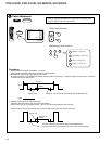
Note that the power may be shut down when the voltages 130 V, 25 V, and 12 V from the POWER SUPPLY Assy are not supplied because the
DEFLECTION SERVICE Assy is powered by the POWER SUPPLY Assy.
When overload detection mechanisms 1 and 2 are activated, the 130 V line is short-circuited. If the power switch is set to ON again in this
condition, there may be a case where the power cannot be turned on, with just a whining sound, and where only the D915 LED in the POWER
SUPPLY Assy is lit. If this happens, first replace only the DEFLECTION SERVICE Assy, disconnect the AC cord from the AC outlet or turn
the main power switch OFF, and wait for five minutes. Then, turn on the power again. If the condition is ameliorated, only the DEFLECTION
SERVICE Assy is defective. If the same symptom occurs, replace the POWER SUPPLY Assy. In the latter case, the DEFLECTION SERVICE
Assy may not be defective.
Be sure to check the fuses in the POWER SUPPLY Assy because one or more may be blown as a result of short-circuiting of the load circuit of
the DEFLECTION SERVICE Assy.