1–Hardware and Software Components
Software Components
FC0054607-00 A 1-3
Software Components
This section describes the following QLogic adapter software components:
Boot Code
OS Driver
Firmware
Management Tools and Utilities
Boot Code
Boot code resides on the Flash memory on the adapter. The primary function of
the boot code is to communicate with an external boot device before the operating
system takes the control over when booting from a storage device attached to the
QLogic adapter. This type of configuration is referred to as boot from SAN.
OS Driver
For all QLogic Fibre Channel Adapters currently supported on VMware ESX/ESXi
4.0, the driver is supported natively with ESX; that is, no separate driver
installation is required for VMware ESX/ESXi 4.0 to recognize the QLogic Fibre
Channel Adapters. QLogic Fibre Channel Adapters on VMware ESX/ESXi 4.0
require no additional driver installation steps to run the adapters. In some specific
cases, you may need to download from the VMware Web site one of the following:
A VMware Approved Driver CD
(
http://driverdownloads.qlogic.com/QLogicDriverDownloads_UI/default.aspx
)
ESX/ESXi patches that might include specific fixes for adapters or enable
new adapters.
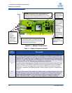
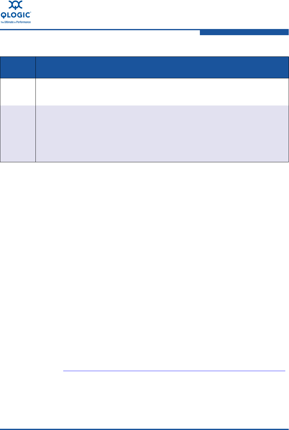
4 LEDs indicate the real-time status of the adapter, Fibre Channel or Ethernet link status, and
link activity. LED patterns are described in detail in “Troubleshooting with LEDs” on
page A-1.
5 Non-volatile random access memory (NVRAM) is used to store the per-port adapter config-
uration parameters. These parameters are typically loaded at manufacturing and should
not be modified except by those who have an expert level understanding of the functioning
of QLogic Fibre Channel and Converged Network Adapters. During adapter initialization,
the parameters are accessed and used to configure the adapter. Examples of adapter con-
figuration parameters include Fibre Channel connection type (topology), Fibre Channel
data rate, Fibre Channel tape support, and so on.
Table 1-1. Adapter Component Details (Continued)
Callout
Number
Description


