


IPmux-1/1E Installation and Operation Manual Appendix E Parameters and Screens
Bundle Connection Configuration E-25
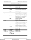
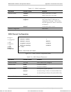
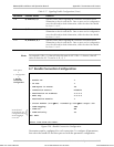
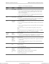
Table E-17. Signaling Profile Configuration (Cont.)
Parameter Possible Values Remarks
Tx B
B, B Inverse, 0, 1
Specifies which ABCD Signaling Bit carries the on hook/off hook
information to the far-end device. One or more can be configured to
carry the off-hook/on-hook information, while the other bits should
be set to ‘1’ or ‘0’.
Tx C
C, C Inverse, 0, 1
Specifies which ABCD Signaling Bit carries the on hook/off hook
information to the far-end device. One or more can be configured to
carry the off-hook/on-hook information, while the other bits should
be set to ‘1’ or ‘0’.
Tx D
D, D Inverse, 0, 1
Specifies which ABCD Signaling Bit carries the on hook/off hook
information to the far-end device. One or more can be configured to
carry the off-hook/on-hook information, while the other bits should
be set to ‘1’ or ‘0’.
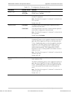
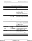
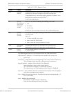
For example, if Rx = A, then all other Rx must be NC. If Rx = A Inverse, then all
other Rx must be NC. Tx can be A, B , 0, 1.
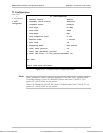
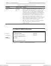
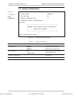
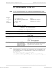
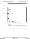
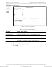
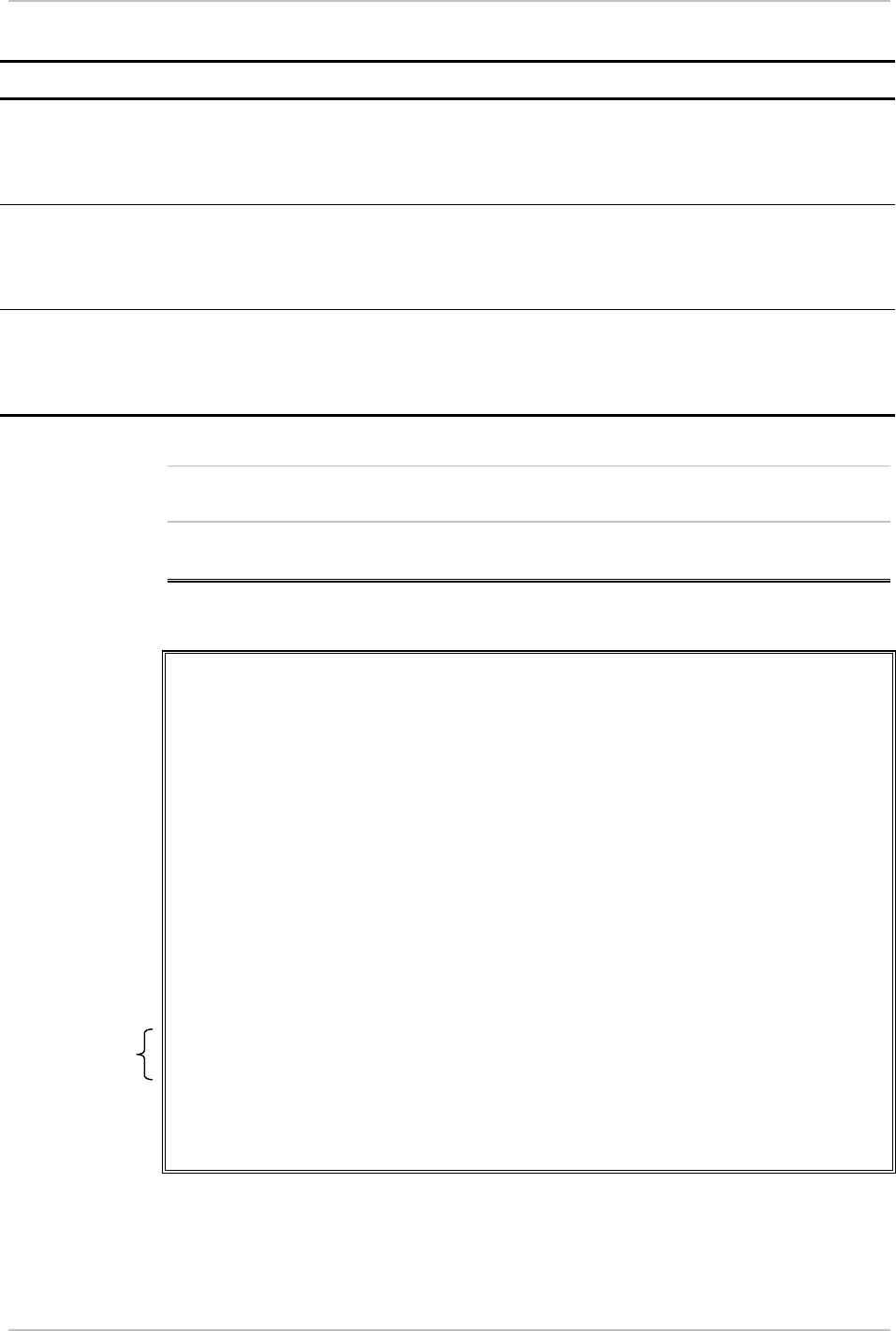
E.7 Bundle Connection Configuration
BUNDLE CONNECTION CONFIGURATION
1. Bundle ID 1
2. IP TOS 1
3. TDM Bytes in Frame 48
4. Connection Status Disable
5. Destination IP Address 0.0.0.0
6. Next Hop 0.0.0.0
7. Destination Bundle 1
8. Jitter Buffer (x10 µ
µµ
µsec) rounded up 1000 µ
µµ
µsec steps! 300
9. VLAN Tagging YES
A. VLAN Id EE
B. VLAN Priority 00
ESC. Exit
Select item from the menu.
Figure E-26. Bundle Connection Configuration
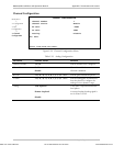
Parameters must be configured for each connection. To configure all parameters,
first select the bundle ID and then proceed with the parameter configuration.
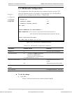
VLAN ID and
VLAN Priority are
configurable only if
VLAN Tagging is
set to Yes.
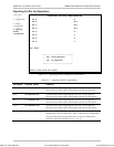
Main Menu
↓
2. Configuration
↓
3. Bundle
Connection
Configuration
Note
Order from: Cutter Networks
Ph:727-398-5252/Fax:727-397-9610
www.bestdatasource.com