


IPmux-1/1E Installation and Operation Manual Chapter 2 Installation
Installation and Setup 2-7
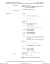
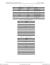
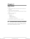
Table 2-1. E1/T1 Port Connectors Pinout
Pin Designation Direction Function
1 RD (R) Input Receive data (ring)
2 RD (T) Input Receive data (tip)
3,6 – – FGND
4 TD (R) Output Transmit data (ring)
5 TD (T) Output Transmit data (tip)
7,8 – N/A Not connected
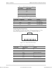
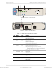
Table 2-2. Ethernet Port Pinout
Pin Pinout
1 Tx+
2 Tx–
3 Rx+
4 –
5 –
6 Rx–
7 –
8 –
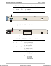
Table 2-3. Control Port Pinout
Pin Pinout
1 –
2 Rx
3 Tx
4 –
5 GND
6 –
7 –
8 –
9 –
Order from: Cutter Networks
Ph:727-398-5252/Fax:727-397-9610
www.bestdatasource.com