


IPmux-1/1E Installation and Operation Manual Chapter 1 Introduction
Functional Description 1-11
Front Panel
The control interface and indicator LEDs are located on the front panel of
IPmux-1/1E. For further details see Chapter 2.
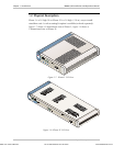
Rear Panel
User and network ports and power supply are located on the rear panel of
IPmux-1/1E. For further details see Chapter 2.
1.3 Functional Description
IPmux-1 supports a single E1 or T1 TDM interface; it provides TDM connectivity
across the IP network. A single bundle (group of timeslots) can be transmitted to a
predefined far-end bundle. IPmux-1 supports ICMP (ping), and generates ARP in
case of unknown next hop MAC addresses, answers ARP requests, and supports
802.3 Ethernet format.
IPmux-1E supports 4 BRI or 4 FXS ports for transparent connectivity over the IP
network.
Both IPmux-1 and IPmux-1E support Ethernet user port for user LAN connectivity.
Configuration and management are provided via the IPmux-1/1E local terminal,
Telnet or RADview management tool (SNMP).
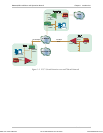
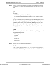
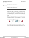
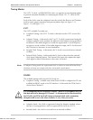
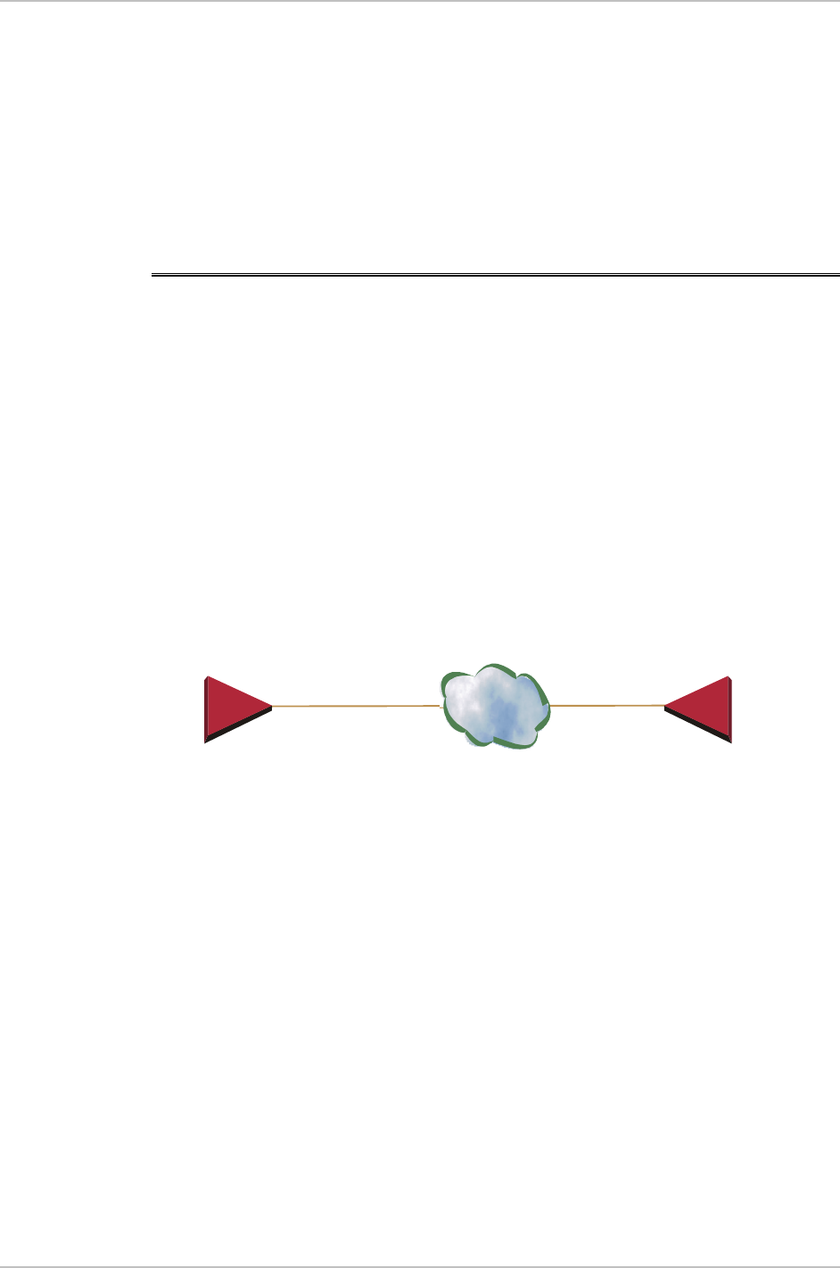
Figure 1-9 shows a typical application for IPmux-1.
IP
IPmux-1
E1/T1 Port
IPmux-1
E1/T1 Port
10/100BaseT
100BaseF 100BaseF
10/100BaseT
Figure 1-9. IPmux-1 Functional Diagram
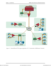
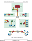
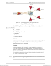
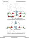
IPmux-1/1E works in conjunction with the rest of the IPmux product line (see
Figure 1-10). The combination of IPmux products provides up to 31 per E1 or
24 per T1 remote bundles, attached to one central IPmux-4/16 (see Figure 1-10).
Order from: Cutter Networks
Ph:727-398-5252/Fax:727-397-9610
www.bestdatasource.com