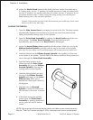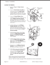
6. If using fanfold labels (or tags) set
them on a flat surface behind the
printer and remove the cover from
the Feed Slot on the rear panel.
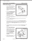
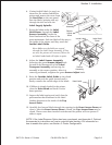
Pass the labels (printing side up)
through the slot and over the
Label Supply Spindle.
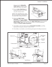
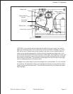
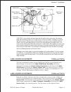
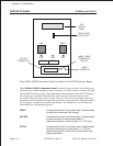
7. Route the labels under the Label
Hold-Down, through the Label
Sensor Assembly, under the
Print Head and out the front of the
print mechanism. Push the labels all the way to
the inside of the printer until they touch the
Inside Label Guide.
Note: Make sure the labels are routed
through the Label Sensor Assembly. If they
are not, the printer will react as if there are
no labels loaded and will refuse to print.
8. Adjust the Label Sensor Assembly
loosening the green Sensor Adjust knob
located on the bottom side of the Label
Transport Assembly and moving the
assembly to the correct position. After it is
correctly positioned, retighten the green Sensor Adjust knob.
9. Raise the Outside Label Guide to the closed
position and push the guide inward until it
barely contacts the outside edge of the labels.
10. If Ribbon is already loaded in the printer,
close the Print Head and latch it in the
down position.
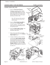
11. Inspect the label routing and verify that the
path matches that illustrated in the Label
Loading diagram on the inside of the Top
Access Door.
12. Carefully feed several labels through the opening in the Front Access Door and
close it. After the Front Access Door is closed, the Top Access Door may be
closed. These covers have interlock switches and the printer will not operate if
either is open.
NOTE: If the Label Dispense Option has been purchased, see Appendix A, Optional
Accessories for instructions on how to route the label backing. For information on
how to enable this option, see Section 3: Printer Configuration.
Section 2. Installation
SATO CL Series “e” Printers PN 9001074 Rev. B Page 2-9
Head Latch
Inside Label
Sensor
Assembly
Label Hold
Down
Sensor
Adjust
Knob
Sensor
Assembly


