


Unit 4: Operation
SATO XL400-410e Operator Manual PN 9001135A Page 4-2
PRINTER CONFIGURATION
The printer may be configured for specific jobs via the operator panel located on the right side of
the printer and the interface panel comprised of three dip switch complexes and four
potentiometers located within the printer’s interior. Each of these must be adjusted for full printer
configuration. The first step is to set the dip switches to their proper positions and then proceed
to the Configuration Modes and Operational Adjustments chapters to complete process.
DIP SWITCH PANELS
The following tables provide guidance on the enabling/disabling of various printer functions and
features. Determine what features are applicable to your setup, or desired setup, and adjust their
respective dip switches as applicable.
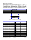
Each dip switch panel is an eight switch complex. Each switch is of a two position on/off toggle
type with the On position always oriented upward. To set the switches, first power the unit off,
then position the dip switches as required. After placing the dip switches in the desired positions,
power the printer back on. The switch settings are read by the printer electronics during the
power up sequence. They will not become effective until the power is cycled.
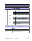
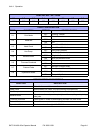
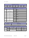
NOTE: There are three dip switch complexes and each are
numbered respectively. Each dip switch complex has eight switches
that are also numbered. Each of the following three tables
represents a single dip switch complex. The left column of each
table identifies the switch number and every column following that,
provides settings information.
CAUTION: NOT ALL OF THE SWITCHES WILL REQUIRE
ADJUSTMENT, CHANGE ONLY THOSE SWITCH SETTINGS
THAT ARE NECESSARY. LEAVE ALL OTHERS AT THEIR
DEFAULT POSITIONS.