


Unit 4: Operation
SATO XL400-410e Operator Manual PN 9001135A Page 4-28
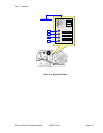
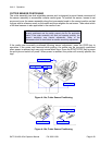
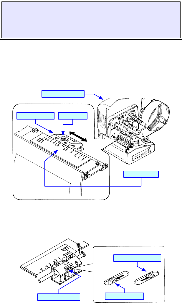
CUTTER SENSOR POSITIONING
The cutter assembly has dual adjustable sensors and is designed to permit lateral movement of
the sensor assembly to accomdate multiple media types. To position the sensor, loosen its set
screw and move the sensor assembly along the incremented scale to the correct position so that
it aligns with its reference mark on the media and then retighten the set screw. Then select which
of the dual sensors is also applicable to the media of use.
If the media was incorrectly positioned following sensor adjustment, press the FEED key to
reposition. If the power was removed while printing, the media may be incorrectly positioned
when power is restored and may print several blank tags. Press the START/STOP key to pause
the print job and switch off power. When power is restored, the printer will correctly position the
tags.
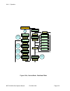
Figure 4-14a, Cutter Sensor Positioning
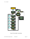
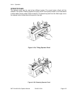
Figure 4-14b, Cutter Sensor Positioning
NOTE: In order for the sensor to function properly, it must be
correctly positioned and the switch properly set for the applicable
media. If the cutter assembly still does not operate correctly, the
sensor’s sensitivity may require adjustment. Refer to the
Maintenance Unit for instructions on sensor sensitivity adjustment.
Sensor Scale
Set Screw
Top Housing Cover
Sensor Assembly
Sensor Switch
R-Corner Media
All Other Media Types