


Unit 6: Maintenance
SATO XL400-410e Operator Manual PN 9001135A Page 6-14
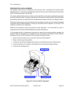
PITCH SENSOR ADJUSTMENT (EYE-MARK MEDIA)
This sensor adjustment regulates penetrating ability for media referencing. Penetration
modification is performed via two potentiometers that is part of the potentiometer complex
located behind the access panel on the left side of the printer.
To establish penetration, upper and lower voltage levels must be set and the difference between
the two voltage levels should be maximized for optimum performance.
These activities require the use of a multimeter and may be perfomed with or without the
assistance of the SATO Test Module. The test module is a purchase option..
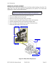
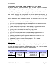
Refer to the procedure below for directions using the test module and Figure 6-11 for visual
assistance.
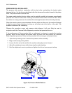
1 Detach the access panel located on the left side of the printer.
2 Adjust the VR8 potentiometer fully counter clock-wise and the VR2 adjusted center scale.
3 Connect the test module to the available test connector.
4 Connect the multimeter ground probe to the pin identified as GRD on the test module.
5 Connect the multimeter positive probe to the pin identified as SIG.
6 Turn the printer on and rotate the test module dial to the 4 position.
7 Physically place the media’s reference point over the pitch sensor.
8 Adjust the VR8 potentiometer until the multimeter displays a value less than +0.5V.
9 Relocate the media so the paper portion is oriented over the pitch sensor.
10 Regard the multimeter to determine the second measurement is greater than +1.5V.
11 Use the VR8 potentiometer for fine adjustment as necessary.
12 Repeat steps 6 through 11 until the required difference of 0.9V is achieved.
13 Begin normal printing to ensure proper adjustment.
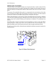
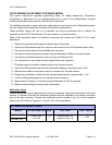
Multimeter Alone
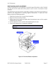
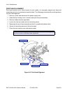
Sensor adjustment may be performed by using a multimeter without the assistance of the test
module. To perform this task the multimeter probes must be attached to the correct connector
pins of the test connector. Connect the multimeter positive probe to pin 1A and the negative
probe to pin 2B. Refer to Figures 6-11 and 6-12 for visual assistance.
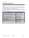
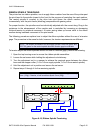
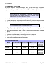
EYE-MARK REFERENCE CHART
MEDIA POTENTIOMETER DIAL TEST PINS VOLT VALUE
Eye-Mark Label
Course: VR2
Fine: VR8
5
Positive Probe: 1A
Negative Probe: 1B
> +0.5V
< +1.5V
Eye-Mark Tag