Unit 6: Maintenance
SATO XL400-410e Operator Manual PN 9001135A Page 6-3
REPLACEMENT PROCEDURES
The printer contains replaceable components and sub-assemblies. This chapter contains step-
by-step instructions for the removal and replacement of those primary components and sub-
assemblies that are subject to wear or damage.
FUSE REPLACEMENT
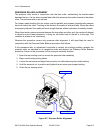
The printer has three fuses; one is externally accessible and is wired to the power supply while
the other two are located internally and directly connected to the main circuit board. Only the
externally accessible fuse is aproved for operator performed replacement.
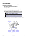
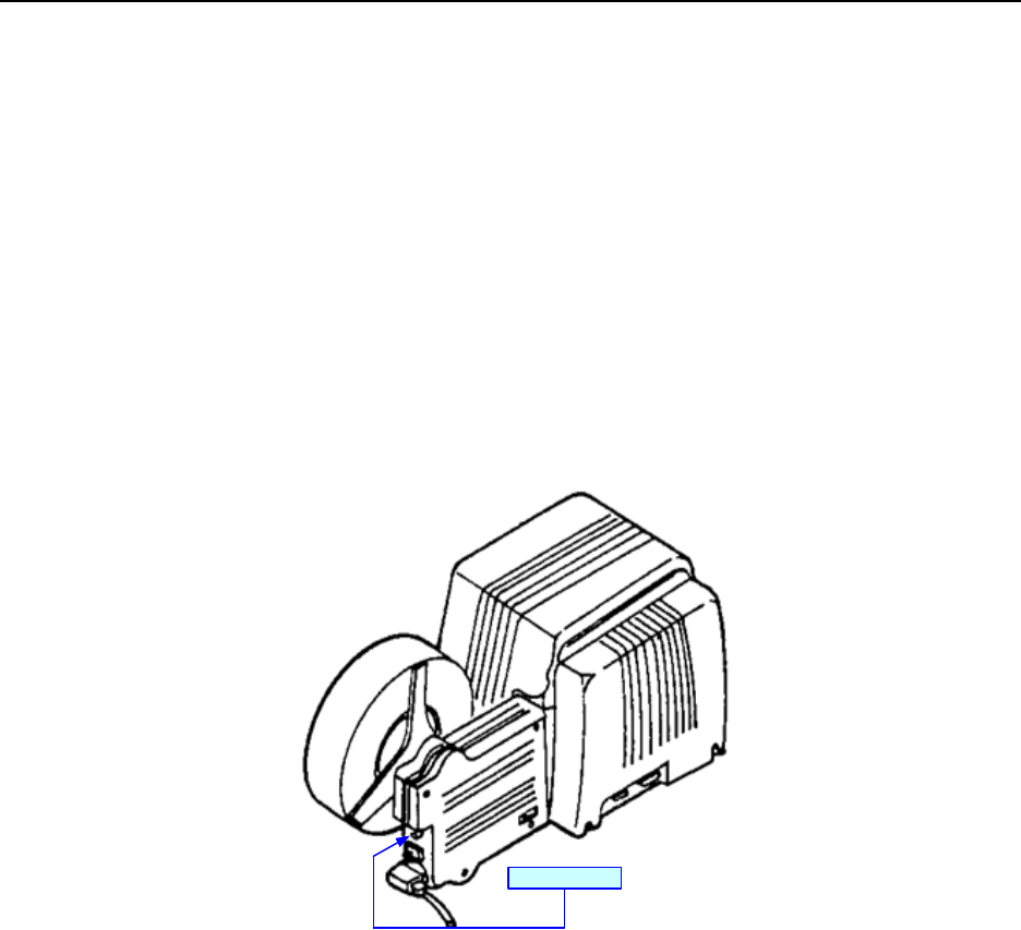
To replace the externally accessible fuse, switch off the printer, disconnect the power supply
cord, and unscrew fuse cap from the fuse connector located on the printer’s back side. Withdraw
the cap along with the fuse and inspect for damage. Insert replacement fuse into the cap and
screw into the fuse connector. Restore power.
Figure 6-2, Fuse Replacement
External Fuse


