Unit 5: Troubleshooting
SATO XL400-410e Operator Manual PN 9001135A Page 5-8
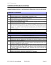
MULTIMETER ALONE
Testing of circuitry and sensor adjustment may be performed by using a multimeter without the
assistance of the test module. To perform this task the multimeter probes must be attached to the
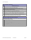
correct connector pins of the test connector. Refer to the table above to correlate the desired
testing or adjustment function with its relative connector pin. Afterward, refer to the table below to
locate the required pins. Refer to the Adjustment Procedures chapter of the Operation unit for
specific adjustment instructions if necessary and applicable.
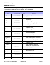
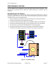
Figure 5-2, Test Connector
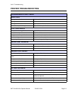
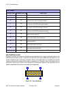
TEST CHART
MODULE DIAL CONNECTOR PIN FUNCTION
1A This test connector pin is used as the ground post.
2A
0 3A
Used to determine voltage of components that require between
+4.8 and +5.2 VDC to properly function.
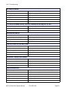
1 4A
Used to determine voltage of components that require between
+11.4 and +12.6 VDC to properly function.
2 5A
Used to determine voltage of components that require between
-11.4 and -12.6 VDC to properly function.
3 6A
Used to determine voltage of components that require between
+23.5 and +24.5 VDC to properly function.
4 1B
Used in cunjunction with potentiometer VR2 to set the eye-mark
media sensor sensitivity.
5 2B
Used in cunjunction with potentiometer VR1 to set the gap or
center hole media sensor sensitivity.
6 3B
Used in cunjunction with potentiometer VR3 to set the ribbon
sensor sensitivity
7 4B
Used in cunjunction with potentiometer VR5 to set the edge-
hole media sensor sensitivity.
8 5B
Used in cunjunction with potentiometer VR6 to set the notched
tag media sensor sensitivity.
6B Used in cunjunction with potentiometer VR7 to set jump sensor.
1A6A
1B6B


