


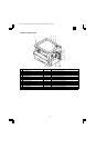
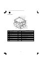
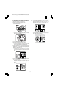
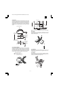
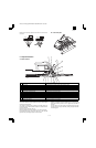

B. Basic structure of scanner section
1 Copy lamp (Xenon lamp) Generate photo energy to scan documents.
2 Reflector (Converging plate) Collects light emitted from the copy lamp and radiate the document.
3 No. 1 mirror Refracts the reflection light from the document to No. 2 mirror.
4 No. 2 mirror Refracts the reflection light from No. 1 mirror.
5 No. 3 mirror Refracts the reflection light from No. 2 mirror.
6 Lens Converges reflected light from the document to form images on the CCD element.
7 No. 2/3 mirror unit Includes No. 2/3 mirror. Driven in synchronization with the copy lamp unit.
8 Copy lamp unit Includes the copy lamp, the reflector, and No. 1 mirror. Driven in synchronization with No. 2/3
mirror unit by the mirror motor.
9 CCD PWB Reflected light (image) formed on the CCD is converted into electrical signals (analog signals)
then into digital signals and sent to the MCU.
10 Mirror motor Drives the copy lamp unit and No. 2/3 mirror unit according to the scanning speed.
11 MHPS (Mirror home position sensor) Detects the home position of No. 2/3 mirror unit.
12 Reference white plate Reference white sheet for scanning documents. The reference line of magnification ratio
adjustment during SIM is also drawn.
13 OC glass Glass table to put a document on it.
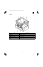
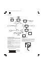
The light from the light source (Xenon lamp) is reflected by a document and passed through three mirrors and reduction lenses to the CCD element
(image sensor) where images are formed. This system is known as the reduction image sensor system. Photo energy on the CCD element is
converted into electrical signals (analog signals). (Photo-electric conversion). The output signals (analog signals) are converted into digital signals
(A/D conversion) and passed to the MCU (main control/image process section). The resolution at that time is 400dpi. The mirror unit in the scanner
section is driven by the mirror motor. The MHPS is provided to detect the home position of the copy lamp unit.
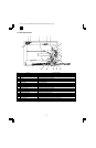
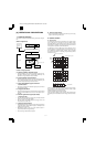
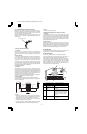
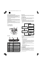
3. Process section
A. Basic structure
1 Main charger unit Charges the OPC drum.
2 Cleaning blade Collects waste toner on the OPC
drum.
3 OPC drum Images are formed by laser beams
electrically, and toner is attached to
the image.
4 Transfer unit Toner on the OPC drum is transferred
to the print paper by the potential
difference.
5 Resist roller Makes synchronization between the
paper and the print image.
6 MG roller Magnetic brush is formed by
developer to put toner on the OPC
drum.
7 (Laser beam) Forms images on the OPC drum.
AR-160/161 FM/E [6] OPERATIONAL DESCRIPTIONS 11/27/1998
AR-161
6 – 2