


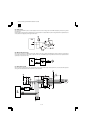

(5) Reset circuit
This circuit detects ON/OFF of power to control start/stop of each circuit. The 5V voltage of the main PWB is detected by the reset IC to generate
the reset signal.
When the power voltage reaches the specified level, the circuit operations are started. Before the power voltage falls below the specified level, the
circuit operations are stopped to prevent against malfunctions.
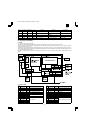
(6) Main motor drive circuit
The main motor is driven by the MMD signal from ASIC. While the main motor is rotating, the MMD signal is driven to HIGH and passed through
IC35 to the control circuit in the main motor to rotate the main motor. The /MMRDY signal is kept HIGH until the main motor speed reaches the
specified rpm, and passed to the CPU.
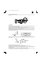
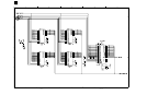
(7) Mirror motor circuit
The mirror motor is a stepping motor, and it uses the IC29 and the constant current chopper control IC (SLA7027). For control, the CPU outputs the
drive signal to the IC29 to drive the mirror motor with 1-2 phase excitement.
AR-161
AR-160/161 FM/E [13] ELECTRICAL SECTION 12/1/1998
13 – 12