


[12] DISASSEMBLY AND
ASSEMBLY
WARNING: Before performing the disassembly procedure, be sure
to remove the power cord to prevent against an electric
shock.
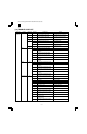
No. Item Page
1 High voltage section 12-1
2 Optical section 12-1
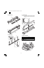
3 Fusing section 12-2
4 Paper exit section 12-4
5 MCU 12-6
6 Optical frame unit 12-6
7 LSU 12-6
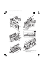
8 Tray paper feed section/Paper transport section 12-7
9 Manual multi paper feed section 12-8
10 Power section 12-10
11 Developing section 12-11
12 Process section 12-12
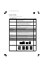
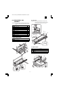
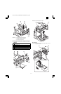
1. High voltage section
No. Content
A Transfer charger unit
B Charger wire
A. Transfer charger unit
B. Charger wire
Installation: The spring tip must be between two reference ribs.
• The charger wire must be free from twist or bending.
• Be sure to put the charger wire in the V groove.
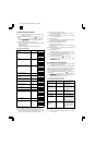
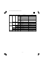
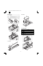
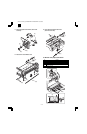
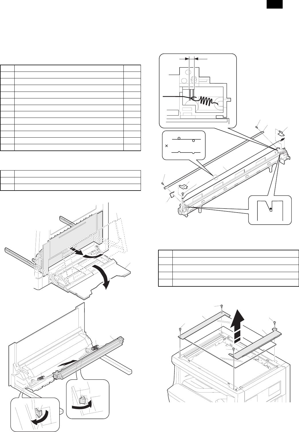
2. Optical section
No. Content
A Table glass
B Copy lamp unit
C Copy lamp
D Lens unit
A. Table glass
(2 )
(1 )
(4 )
(3 )
(3 )
(5 )
(5 )
(2 )
(1 )
(1 )
(1 )
(1 )
(1 )
(1 )
(3 )
(1 )
(1 )
(2 )
(3 )
(3 )
(4 )
AR-160/161 FM/E [12] DISASSEMBLY AND ASSEMBLY 10/16/1998
AR-161
12 – 1