


[7] ADJUSTMENTS
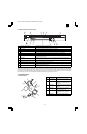
1. Adjustment item list
Section Adjustment item Adjustment procedure/SIM No.
A Process section (1) Developing doctor gap adjustment Developing doctor gap adjustment
(2) MG roller main pole position adjustment MG roller main pole position adjustment
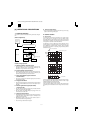
(3) Developing bias voltage output adjustment SIM 8-1
(4) Main charger voltage output adjustment SIM 8-2/SIM 8-3
(5) Transfer charger current adjustment SIM 8-6
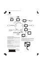
B Mechanism section (1) Image position adjustment SIM 50-1/SIM 50-10
(2) Main scanning direction (FR direction)
distortion balance adjustment
No. 2/3 mirror base unit installing position
adjustment
Copy lamp unit installing position adjustment
(3) Main scanning direction (FR direction)
distortion adjustment
F rail height adjustment
(4) Sub scanning direction (scanning direction)
distortion adjustment
Winding pulley position adjustment
(5) Main scanning direction (FR direction)
magnification ratio adjustment
SIM 48-1
(6) Sub scanning direction (scanning direction)
magnification ratio adjustment
a OC mode in copying (SIM 48-2)
b SPF mode in copying (SIM 48-5)
c OC mode in FAX (SIM 48-6)
d SPF mode in FAX (SIM 48-7)
(7) Off center adjustment a OC mode (SIM 50-13)
b SPF mode (SIM 50-16)
(8) Document size detection sensor SIM 41-2
C Image density adjustment (1) Copy mode SIM 46-1
2. Copier adjustment
A. Process section
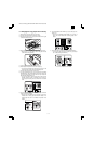
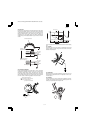
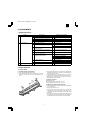
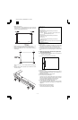
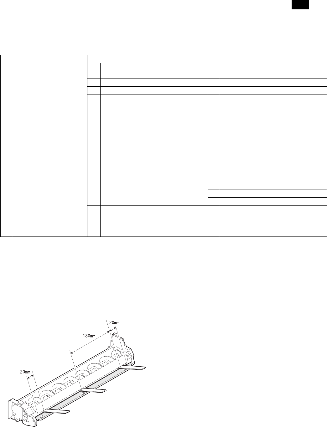
(1) Developing doctor gap adjustment
1) Loosen the developing doctor fixing screw A.
2) Insert a thickness gauge of 1.5mm to the three positions at 20mm
and 130mm from the both ends of the developing doctor as
shown.
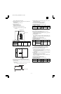
3) Push the developing doctor in the arrow direction, and tighten the
developing doctor fixing screw. (Perform the same procedure for
the front and the rear frames.)
4) Check the clearance of the developing doctor. If it is within the
specified range, then fix the doctor fixing screw with screw lock.
* When inserting a thickness gauge, be careful not to scratch the
developing doctor and the MG roller.
<Adjustment specification>
Developing doctor gap
Both ends (20mm from the both ends): 1.5±0.1mm
C (Center)(150mm from the both ends): 1.5±0.1mm
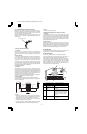
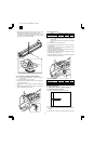
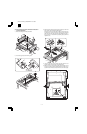
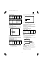
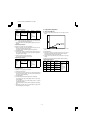
(2) MG roller main pole position adjustment
1) Remove and separate the waste toner box and put the developing
unit on a flat surface.
2) Tie a string to a needle or a pin.
3) Hold the string and bring the needle close to the MG roller
horizontally. (Do not use paper clip, which is too heavy to make a
correct adjustment.) (Put the developing unit horizontally for this
adjustment.)
4) Do not bring the needle into contact with the MG roller, but bring it
to a position 2 or 3mm apart from the MG roller. Mark the point on
the MG roller which is on the extension line from the needle tip.
AR-161
AR-160/161 FM/E [7] ADJUSTMENT 11/27/1998
7 – 1