


MP875 Modem User Guide
58 2130808
Beforeusingthedigitalinput/outputlines,youmustconfigure
themasinputsoroutputs.
Connector pinouts
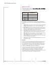
TheMPmodem’sI/OportisafemaleDB15HDconnectorwith
eightactiveI/Opins:
• Two(2)digitalI/Opins.
• Two(2)digitalinputpins.
• Four(4)analoginputpins.
Therearealsosixreservedpinsandonegroundpin.
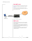
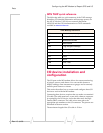
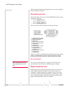
Figure 6-1: Pinouts for a male DB15HD I/O cable (left) that connects to the MP
modem’s female DB15HD I/O connector (right). Note that the two figures’
pinouts are mirror images of each other, since they plug into one another.
Port specifications
Note: No more than 36 VDC
should be applied to any I/O
pins.
See“I/Oportcharacteristics”onpage75forthetechnical
specificationsoftheI/Oports,includinginputvoltages.
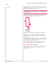
Digital input devices
Digitalinputdevicesarethosethathaveonlytwostatesand
sendasignaltotheMPmodeminoneofthosestates.An
exampleofadigitalinputdevicemightbeagunrackalarm
thatsendsasignaltotheMPmodemanytimethegunrackis
open.
Anotherexamplewouldbeapanicbuttonthatsendsa
signaltotheMPmodemwhenitispushed.
2.
Reserved—do not connect
3. Digital Input/Output 1
4. Digital Input 3
5.
Reserved—do not connect
6.
Reserved—do not connect
7. Analog Input 2
8. Analog Input 4
9.
Reserved—do not connect
10. Ground (GND)
11. Digital Input/Output 2
12. Digital Input 4
13.
Reserved—do not connect
14. Analog Input 1
15. Analog Input 3
1.
Reserved—do not connect
1
6
5
11
10
15
DB15HD female connector
DB15HD male cable
on rear of MP modem