


15
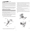
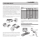
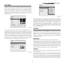
HT300 E-LINK system consists of the Projector and the Di-
giOptic™ Image Processor (which is also the system control
centre). The DigiOptic™ Image Processor sends commands to
the Projector and receives operating status information from the
Projector and function commands from the user. The system can
be controlled from either the remote control (via the infrared sen-
sors on the DigiOptic™ Image Processor and on the Projector)
or the keypad located on the rear of the Projector.
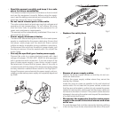
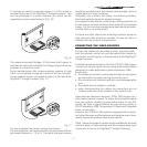
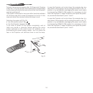
The two units have separate power supplies however: after
connecting the unit to the electrical mains supply:
1) Set the two power switches to “I”; the DigiOptic™ Image
Processor power switch is located on the external power supply
unit (Fig. 13c), while the Projector switch is on the rear panel
(Fig. 13a).
2) Turn on the DigiOptic™ Image Processor by pressing the
button on the front panel
(Fig. 13b).
1
2
C
L
A
S
S
1
L
A
S
E
R
P
R
O
D
UC
T
3
-
O
I
O
I
IMAG
E
P
R
O
C
E
SSO
R
O
FF
ON
D
IG
I
O
P
T
I
C
™
IMA
G
E
P
R
O
C
E
S
S
O
R
O
F
F
ON
After a few seconds (system initialisation interval), the DigiOp-
tic™ Image Processor and the Projector assume stand-by
mode.
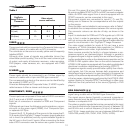
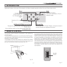
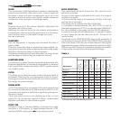
System status information is provided by two LEDs (green and
blue) on the front panel of the DigiOptic™ Image Processor, a
blue and green LEDS on the rear of the Projector.
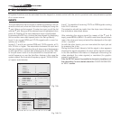
Significant status signals are given in Table 3.
Table 3
Off
Initialisation
Status
DigiOptic Image
Processor
Projector
Green LED Blue LED Green LED Blue LED
Stand-by
On
Cooling
Optical link not active
Caution
Error
: Of
f
: On
: Flashing
: Insignificant
-
-
-
- -
If the “No optical link” or “Error” signals are active the system
cannot be operated; if the “Warning” signal is active the system
will operate but it may be unable to read certain input signals
correctly.
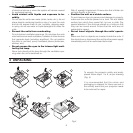
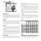
SWITCHING ON FROM STAND-BY
Switching on the system (Fig.14):
• from the remote control (keys 0-9)
• from the Projector keypad (keys
· and ‚).
RC
I 2005
LI
G
H
T
?
?
?
0
Fig.14
5 SWITCHING ON/OFF