


9
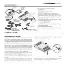
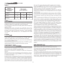
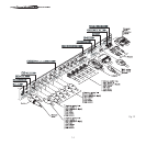
The carton should contain the following:
- the projector
- the DigiOptic™ Image Processor
- the remote control
- four 1.5V AAA batteries (for remote control)
- DigiOptic™ Image Processor power supply unit
- three power cables for the projector (EU, UK, USA)
- three power cables for the DigiOptic™ Image Pro
-
cessor (EU, UK, USA)
- triple fiber optic cable for linking DigiOptic™ Image
Processor and the projector
- one cable HDMI™-HDMI™
- one cable HDMI™-DVI
- two brackets for mounting the DigiOptic™ Image
Processor to the rack.
- the user and installation manual.
If any accessories are missing, contact your Dealer as
soon as possible.
PACKAGE CONTENTS
DIGIOPTIC ™ IMAGE PROCESSOR
OFF
ON
DigiOptic™ Image
Processor power
supply unit
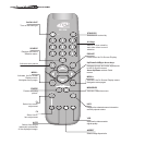
Remote Control
1.5 V AAA-
type batteries
Support
Power cables
Europe, UK, US (x2)
DigiOptic™
Image Processor
Three-core
fibre optic cable
Instruction
Manual
O
I
Projector
Cable HDMI™-HDMI™
Cable HDMI™-DVI
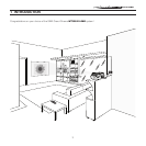
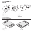
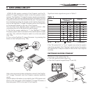
4 INSTALLATION
POSITIONING THE TWO UNIT
The HT300 E-LINK system consists of two separate units (the
DigiOptic™ Image Processor and the Projector), each of which
is equipped with a power cable; the two units are interconnected
by a 20 m fibre optic cable.
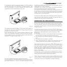
The ideal location for the DigiOptic™ Image Processor is on a
cabinet shelf or on a rack (dimensions compatible with a stan
-
dard 19” rack). Make sure that the support surface is stable
and that the unit has sufficient space around it for ventilation
purposes (at least 3 cm). The unit is connected to the mains
via an external power supply unit with an output of +7 Vdc; the
unit’s main power switch is on the power supply unit.
Connect the power supply unit output cable to the POWER
socket located on the rear panel
(Fig. 2).
Use exclusively the power supply unit provided with the sy
-
stem or an alternative power supply unit expressly approved
by SIM2.
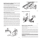
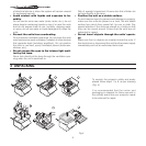
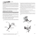
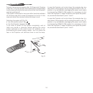
To mount the DigiOptic Image Processor on an equipment
rack use the screws and RH / LH supports supplied with the
appliance. Unscrew the screws that secure the cover to the
DigiOptic unit base, position the RH and LH supports and fix
into place with the supplied screws. To secure the unit to the
rack use the supplied screws
(Fig.6).
DIGIOPTIC ™ IMAGE PRO
CESSOR
OFF
ON
Fig.6
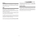
Position the projector on a stable, suitable platform or utilise the
optional bracket for a fixed ceiling or wall installation.
Fig.5