


42 MI.20xx Manual
Setting up the inputs Analog Inputs
Setting up the inputs
Input ranges
This analog acquisition board uses separate input amplifiers and converters on each channel. This gives you the possibility to set up the de-
sired and concerning your application best suiting input range also separately for each channel. The input ranges can easily be set by the
corresponding input registers. The table below shows the available input registers and possible ranges for your type of board.
The different input ranges are set with the help of relais. These relais need a settling time if they are changed, so that the relais are fully set
and didn’t influence the signal when the board is started. The following table shows the related register to adjust the wait time. Any changes
of the wait time below the default value should only be done after detailed tests of the boards behaviour. Setting lower values may be possible
or may not be possible depending on the application that is done.
If you want to know, how many different input ranges are available on the actual board per channel, you can easily read that information
by using the read-only register shown in the table below.
Additionally cou can read out the minimum and the maximum value of each input range as shown in the table below. The number of input
ranges is read out with the above shown register.
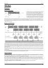
The following example reads out the number of available input ranges and reads and prints the minimum and maximum value of all input
ranges.
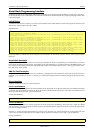
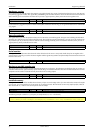
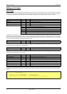
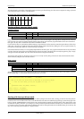
Register Value Direction Description
SPC_AMP0 30010 r/w Defines the input range of channel0.
SPC_AMP1 30110 r/w Defines the input range of channel1.
SPC_AMP2 30210 r/w Defines the input range of channel2.
SPC_AMP3 30310 r/w Defines the input range of channel3.
50 ± 50 mV calibrated input range for the appropriate channel.
100 ± 100 mV calibrated input range for the appropriate channel.
200 ± 200 mV calibrated input range for the appropriate channel.
500 ± 500 mV calibrated input range for the appropriate channel.
1000 ± 1 V calibrated input range for the appropriate channel.
2000 ± 2 V calibrated input range for the appropriate channel.
5000 ± 5 V calibrated input range for the appropriate channel.
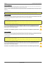
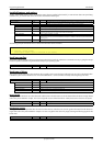
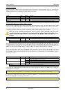
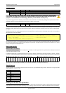
Register Value Direction Description
SPC_RELAISWAITTIME 200700 r/w Wait time in ms for relais settling before the start of the board. Default value is 200 ms.
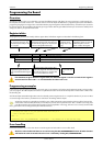
Register Value Direction Description
SPC_READIRCOUNT 3000 r Informs about the numer of the board’s calibrated input ranges.
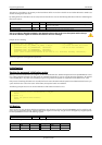
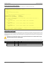
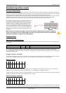
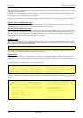
Register Value Direction Description
SPC_READRANGEMIN0 4000 r Gives back the minimum value of input range 0 in mV.
SPC_READRANGEMIN1 4001 r Gives back the minimum value of input range 1 in mV.
SPC_READRANGEMIN2 4002 r Gives back the minimum value of input range 2 in mV.
... ... r ...
SPC_READRANGEMAX0 4100 r Gives back the maximum value of input range 0 in mV.
SPC_READRANGEMAX1 4101 r Gives back the maximum value of input range 1 in mV.
SPC_READRANGEMAX2 4102 r Gives back the maximum value of input range 2 in mV.
... ... r ...
SpcGetParam (hDrv, READIRCOUNT, &lNumberOfRanges);
for (i = 0; i < lNumberOfRanges; i++)
{
SpcGetParam (hDrv, SPC_READRANGEMIN0 + i, &lMinimumInputRage);
SpcGetParam (hDrv, SPC_READRANGEMAX0 + i, &lMaximumInputRange);
printf („Range %d: %d mV to %d mV\n“, i, lMinimumInputRange, lMaximumInputRange);
}