


64 MI.20xx Manual
Channel Trigger Trigger modes and appendant registers
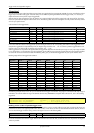
The resulting trigger step width in mV can easily be calculated from the returned
value. It is assumed that you know the actually selected input range.
To give you an example on how to use this formular we assume, that the
±1.0 V input range is selected and the board uses 8 bits for trigger detection.
The result would be 7.81 mV, which is the step width for your type of board withing the actually chosen input range.
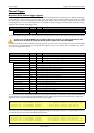
Trigger step width
Input Range
max
Input Range
min
–
Number of trigger levels 1+
---------------------------------------------------------------------------------
=
Trigger step width
+1000 mV (-1000 mV)–
255 1+
------------------------------------------------------------
=