


96 MI.20xx Manual
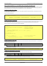
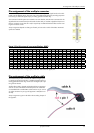
Pin assignment of the internal multipin connector
Pin assignment of the internal multipin connector
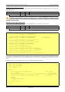
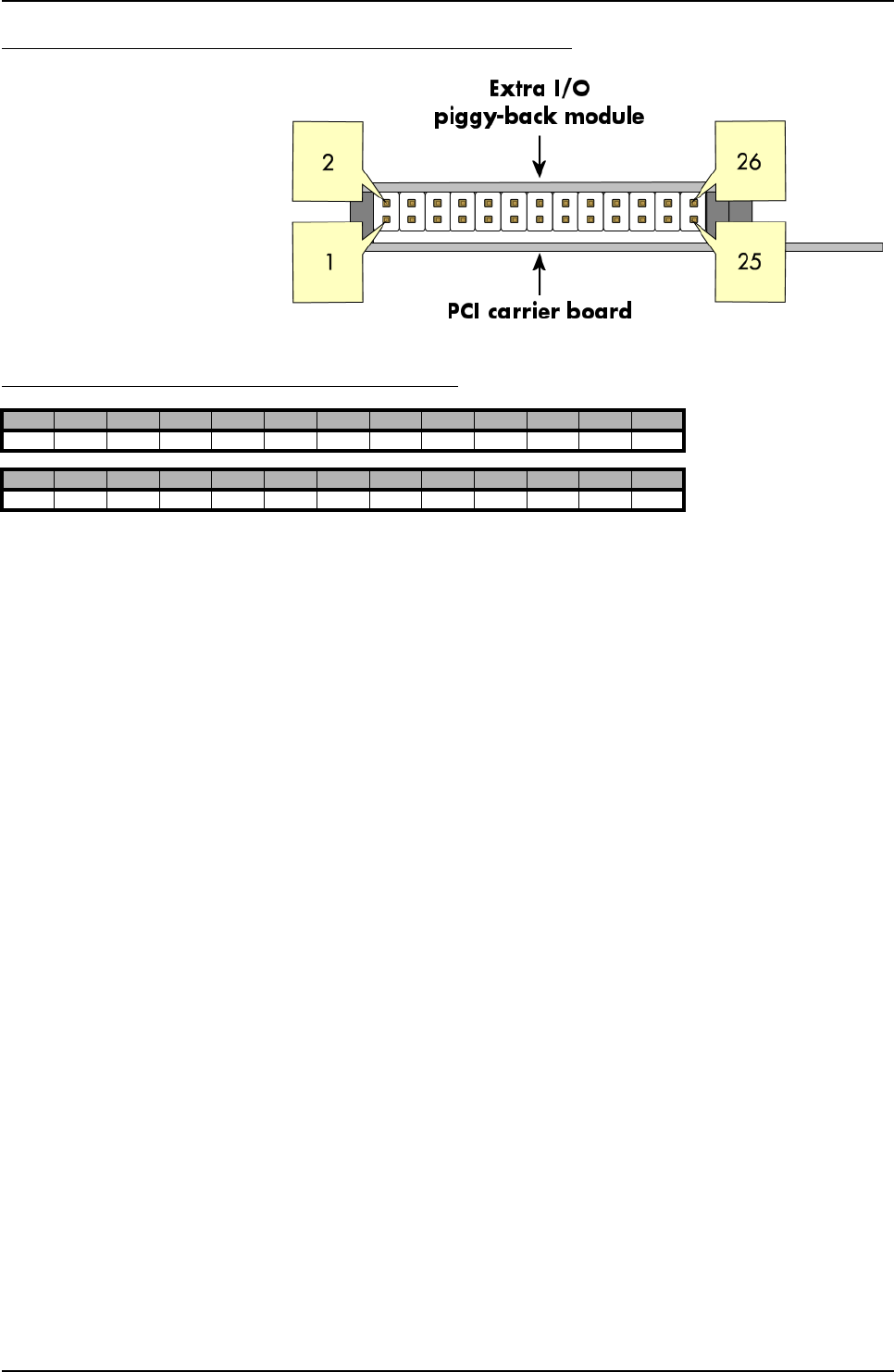
The 26 lead internal connector is used for
the option “Extra I/O“ (-XIO) without the
external connector described before.
The connector mentioned here is mounted
on the bottom side of the Extra I/O modu-
le.
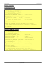
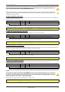
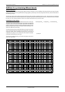
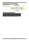
Extra I/O with internal connector (Option -XIO)
A3…A0 are the pins for the analog outputs, while D15…D0 are the 16 digital I/Os.
Pin2 Pin4 Pin6 Pin8 Pin10 Pin12 Pin14 Pin16 Pin18 Pin20 Pin22 Pin24 Pin26
A2 A0 GND D14 D12 D10 D8 GND D6 D4 D2 D0 GND
Pin1 Pin3 Pin5 Pin7 Pin9 Pin11 Pin13 Pin15 Pin17 Pin19 Pin21 Pin23 Pin25
A3 A1 GND D15 D13 D11 D9 GND D7 D5 D3 D1 GND