


Trigger modes and appendant registers Channel Trigger
(c) Spectrum GmbH 65
Detailed description of the channel trigger modes
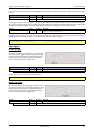
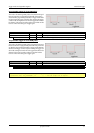
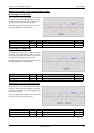
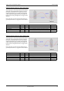
Channel trigger on positive edge
The analog input is continuously sampled with the selected
sample rate. If the programmed triggerlevel is crossed by
the channel’s signal from lower values to higher values (ri-
sing edge) then the triggerevent will be detected.
These edge triggered channel trigger modes correspond to
the trigger possibilities of usual ocilloscopes.
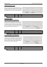
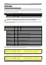
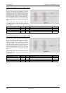
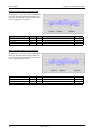
Channel trigger on negative edge
The analog input is continuously sampled with the selected
sample rate. If the programmed triggerlevel is crossed by
the channel’s signal from higher values to lower values (fal-
ling edge) then the triggerevent will be detected.
These edge triggered channel trigger modes correspond to
the trigger possibilities of usual ocilloscopes.
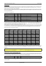
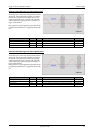
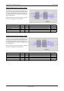
Channel trigger on positive and negative edge
The analog input is continuously sampled with the selected
sample rate. If the programmed triggerlevel is crossed by
the channel’s signal (either rising or falling edge) the trigge-
revent will be detected.
These edge triggered channel trigger modes correspond to
the trigger possibilities of usual ocilloscopes.
Register Value Direction set to Value
SPC_TRIGGERMODE 40000 r/w TM_CHANNEL 20040
SPC_TRIGGERMODE0 40200 r/w TM_CHXPOS 10000
SPC_HIGHLEVEL0 42000 r/w Set it to the desired triggerlevel relatively to the channel’s input range. board dependant
Register Value Direction set to Value
SPC_TRIGGERMODE 40000 r/w TM_CHANNEL 20040
SPC_TRIGGERMODE0 40200 r/w TM_CHXNEG 10010
SPC_HIGHLEVEL0 42000 r/w Set it to the desired triggerlevel relatively to the channel’s input range. board dependant
Register Value Direction set to Value
SPC_TRIGGERMODE 40000 r/w TM_CHANNEL 20040
SPC_TRIGGERMODE0 40200 r/w TM_CHXBOTH 10030
SPC_HIGHLEVEL0 42000 r/w Set it to the desired triggerlevel relatively to the channel’s input range. board dependant