


80 MI.20xx Manual
Reading out timestamp data Option Timestamp
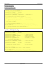
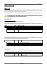
Reading out all the timestamps with SpcGetData
When using the function SpcGetData the data stored in the timestamp FIFO will be read out in one block by the driver. The usage of the
function SpcGetData is described in the relating section earlier in this manual. The following list does only show the different parameters in
a very short way:
SpcGetData (nr, ch, start, len, data)
• nr: Number of the board (Windows). Linux users please refer to the Driver section for differences using linux.
• ch: Channel to be read out. Must be set to CH_TIMESTAMP (9999) to access timestamp FIFO.
• start: Differing from the standard use, this parameter gives back the number of actually read timestamps and therefore needs to be a poin-
ter. Please refer to the example at the end of this chapter.
• len: Number of timestamps that fit in the data buffer and so defines the number of timestamps to be read out.
• data: Huge buffer for the read out timestamps, that must have at least enough space for 8*len bytes.
It might be that you try to read out more timestamps than there actually are in the timestamp FIFO bacause you don’t know how many trigger
events have been detected. Please make use of the value given back by the parameter start to get to know what parts of your buffer contain
valid timestamps.
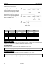
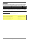
Data format
Each timestamp is 56 bit long and internally mapped to 64 bit (8 bytes). The counter value contains the number of clocks that have been
recorded with the currently used sample rate since the last counter-reset has been done. The matching time can easily be calculated as des-
cribed in the general information section at the beginning of this chapter.
The values the counter is counting and that are stored in the timestamp FIFO represent the moments the trigger event occures internally. Com-
pared to the real external trigger event, these values are delayed. The delay is depending on the actual sample rate, the number of activated
channels and the used trigger mode. This delay can be ignored, as it will be identically for all recordings with the same setup.
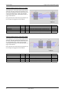
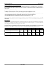
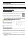
Timestamp Mode Recording Mode
1
st
4 bytes 2
nd
4 bytes 3
rd
4 bytes 4
th
4 bytes 5
th
4 bytes 6
th
4 bytes
Standard/StartReset Normal / Multiple Recording Trigger 0
LOW part
Trigger 0
HIGH part
Trigger 1
LOW part
Trigger 1
HIGH part
Trigger 2
LOW part
Trigger 2
HIGH part
Standard/StartReset Gated Sampling Gate Start 0
LOW part
Gate Start 0
HIGH part
Gate End 0
LOW part
Gate End 0
HIGH part
Gate Start 1
LOW part
Gate Start 1
HIGH part
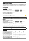
RefClock Normal / Multiple Recording Trigger 0
Counter value
Trigger 0
Seconds
Trigger 1
Counter value
Trigger 1
Seconds
Trigger 2
Counter value
Trigger 2
Seconds
RefClock Gated Sampling Gate Start 0
Counter value
Gate Start 0
Seconds
Gate End 0
Counter value
Gate End 0
Seconds
Gate Start 1
Counter value
Gate Start 1
Seconds