


Option Gated Sampling Example program
(c) Spectrum GmbH 77
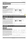
Channel trigger
Example program
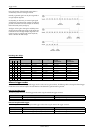
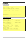
The following example shows how to set up the board for Gated Sampling in standard mode. The setup would be similar in FIFO mode, but
the memsize register would not be used.
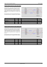
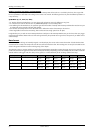
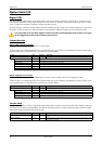
Mode Gate start will be detected on Gate end will be detected on
TM_CHXPOS signal crossing level from low to high signal crossing level from high to low
TM_CHXNEG signal crossing level from high to low signal crossing level from low to high
TM_CHXPOS_LP signal above level longer than the programmed pulsewidth signal crossing level from high to low
TM_CHXNEG_LP signal below level longer than the programmed pulsewidth signal crossing level from low to high
TM_CHXWINENTER signal entering window between levels signal leaving window between levels
TM_CHXWINENTER_LP signal entering window between slower than the programmed pulsewidth signal leaving window between levels
TM_CHXWINLEAVE signal leaving window between levels signal entering window between levels
TM_CHXWINLEAVE_LP signal leaving window between slower than the programmed pulsewidth signal entering window between levels
SpcSetParam (hDrv, SPC_GATE, 1); // Enables Gated Sampling
SpcSetParam (hDrv, SPC_MEMSIZE, 4096); // Set the total memsize for recording to 4096 samples
SpcSetParam (hDrv, SPC_TRIGGERMODE, TM_TTLPOS); // Sets the gate condition to external TTL mode, so that
// recording will be done, if the signal is at HIGH level