


76 MI.20xx Manual
Trigger modes Option Gated Sampling
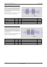
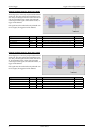
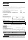
Due to the structure of the on-board memory there is
another delay at the end of the gate interval.
Internally a gate-end signal can only be recognized at
an eight samples alignment.
So depending on what time your external gate signal
will leave the programmed gate condition it might hap-
pen that at maximum seven more samples are recorded,
before the board pauses (see figure).
The figure on the right is showing this end delay exem-
plarily for three possible gate signals. As all samples are
counted from zero. The eight samples alignment in the
upper two cases is reached at the end of sample 39,
which is therefore the 40th sample.
Resulting start delays
Allowed trigger modes
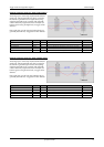
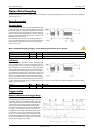
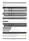
As mentioned above not all of the possible trigger modes can be used as a gate condition. The following table is showing the allowed trigger
modes that can be used and explains the event that has to be detected for gate-start end for gate-end.
External TTL edge trigger
The following table shows the allowed trigger modes when using the external TTL trigger connector:
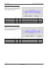
External TTL pulsewidth trigger
The following table shows the allowed pulsewidth trigger modes when using the external TTL trigger connector:
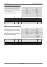
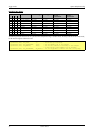
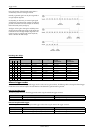
Activated channels Sample rate external TTL trigger internal trigger ext. TTL trigger with
activated
synchronization
internal trigger with
activated
synchronization
0 1 2 3
x < 10 MS/s +22 samples +31 samples +24 samples +33 samples
x(10 < SR < 100) MS/s +23 samples +21 samples +25 samples +23 samples
x> 100 MS/s +16 samples +32 samples +18 samples +34 samples
x x < 5 MS/s -5 samples +5 samples -3 samples +7 samples
xx > 5 MS/s +8 samples +16 samples +10 samples +18 samples
x x < 10 MS/s +22 samples +31 samples +24 samples +33 samples
xx(10 < SR < 100) MS/s +23 samples +21 samples +25 samples +23 samples
xx> 100 MS/s +16 samples +32 samples +18 samples +34 samples
x x x x < 5 MS/s -5 samples +5 samples -3 samples +7 samples
xxxx> 5 MS/s +8 samples +16 samples +10 samples +18 samples
Mode Gate start will be detected on Gate end will be detected on
TM_TTLPOS positive edge on external trigger negative edge on external trigger
TM_TTL_NEG negative edge on external trigger positive edge on external trigger
Mode Gate start will be detected on Gate end will be detected on
TM_TTLHIGH_LP high pulse of external trigger longer than programmed pulsewidth negative edge on external trigger
TM_TTLLOW_LP low pulse of external trigger longer than programmed pulsewidth positive edge on external trigger