


Synchronization (Option) The setup order for the different synchronization options
(c) Spectrum GmbH 89
Setup synchronization for use with FIFO mode and equally clocked boards
Most of the steps are similar to the setup routine for standard synchronization mentioned before. In this passage only the differences between
the two modes are shown. Please have a look at the passage before to see the complete setup procedure. The following steps differ from
standard mode to FIFO mode. All steps that are not mentioned here are similar as described before.
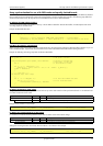
(2) Allocate the FIFO software buffers
If you use the board in FIFO mode additional memory in the PC RAM is needed for software FIFO buffers. For details please refer to the
according chapter for the FIFO mode.
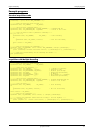
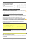
Example of FIFO buffer allocation:
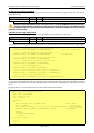
(2a) Write first data for output boards
When using the synchronization FIFO mode with output boards this is the right position to fill the first software buffers with data. As you can
read in the FIFO chapter, output boards need some data to be written to the software FIFO buffers before starting he board.
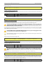
Example of calulcating and writing output data to software FIFO buffers:
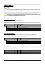
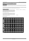
(6) Define the board for clock master
Using the synchronization option requires one board to be set up as the clock master for all the synchronized board. It is not allowed to set
more than one board to clock master.
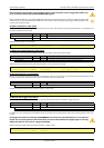
Example: board number 0 is clock master
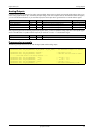
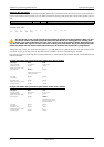
(7) Define the remaining boards as clock slaves
It is necessary to set all the remaining boards to clock slaves to obtain correct internal driver settings.
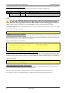
Settings the remaining boards to clock slaves. Board number 0 is clock master in the example
for (i = 0; i < FIFO_BUFFERS; i++)
for (b = 0; b < 3; b++)
{
pnData[b][i] = (ptr16) GlobalAlloc (GMEM_FIXED, FIFO_BUFLEN); // allocate memory
SpcSetParam (b, SPC_FIFO_BUFADR0 + i, (int32) pnData[b][i]); // send the adress to the driver
}
// ----- data calculation routine -----
int g_nPos =0; // some global variables
void vCalcOutputData (ptr16 pnData, int32 lBufsize) // function to calculate the
{ // output data. In this case
int i; // a sine function is used.
for (i = 0; i < (lBufsize/2); i++)
pnData[b][i] = (int16) (8191.0 * sin (2 * PI / 500000 * (g_nPos+i)));
g_nPos += lBufsize/2;
}
// ----- main task -----
int main(int argc, char **argv)
{
...
for (i =0; i < MAX_BUF; i++) // fill the first buffers with data
for (b = 0; b < 3; b++) // for all installed boards
vCalcOutputData (pnData[b][i], BUFSIZE);
...
}
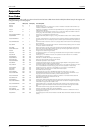
Register Value Direction Description
SPC_COMMAND 0 r/w Command register of the board
SPC_SYNCMASTERFIFO 102 Defines the according board as the clock master for operating in FIFO mode only.
SpcSetParam (hDrv[0], SPC_COMMAND, SPC_SYNCMASTERFIFO); // Set board 0 to clock master
Register Value Direction Description
SPC_COMMAND 0 r/w Command register of the board
SPC_SYNCSLAVEFIFO 102 Defines the according board as a clock slave for operating in FIFO mode only.
SpcSetParam (hDrv[1], SPC_COMMAND, SPC_SYNCSLAVEFIFO); // Setting all the other boards to
SpcSetParam (hDrv[2], SPC_COMMAND, SPC_SYNCSLAVEFIFO); // clock slave is a must !