


Trigger modes and appendant registers Channel Trigger
(c) Spectrum GmbH 63
Triggerlevel
All of the channel trigger modes listed above require at least one triggerlevel to be set (except TM_CHXOFF of course). Some like the window
trigger require even two levels (upper and lower level) to be set. Before explaining the different channel trigger modes, it is necessary to
explain the board’s series specific range of triggerlevels.
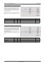
After the data has been sampled, the upper N data bits are compared with the N bits of the trigger levels. The amount of bits, the trigger
levels are represented with depends on the board’s series. The following table shows the level registers and the possible values they can be
set to for your specific board.
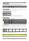
6 bit resolution for the trigger levels:
In the above table the values for the triggerlevels represent the digital values for the corresponding data width N of the triggerlevels. If for
example the triggerlevels are represented by 8 bit, the bipolar range would be -128 … 127. To archieve symmetric triggerlevels the most
negative value is not used and the so resulting range would be -127 … +127.
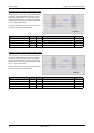
As the triggerlevels are compared to the digitized data, the triggerlevels depend on the channels input range. For every input range available
to your board there is a corresponding range of triggerlevels. On the different input ranges the possible stepsize for the triggerlevels differs
as well as the maximum and minimum values. The following table, gives you the absolute triggerlevels for your specific board’s series.
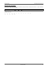
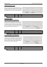
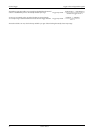
Resulting ranges of the 6 bit trigger level resolution:
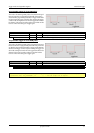
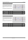
The following example shows, how to set up a one channel board to trigger on channel0’s rising edge. It is asumed, that the input range of
channel0 is set to the the ±200 mV range. The dezimal value for SPC_HIGHLEVEL0 corresponds then with 75.6 mV, wich is the resulting
triggerlevel.
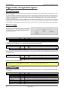
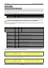
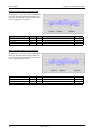
Reading out the number of possible trigger levels
The Spectrum driver also contains a register, that holds the value of the maximum possible different trigger levels considering the above men-
tioned exclusion of the most negative possible value. This is useful, as new drivers can also be used with older hardware versions, because
you can check the trigger resolution during runtime. The register is shown in the following table:
In case of a board that uses 8 bits for trigger detection the returned value would be 255, as either the zero and 127 positive and negative
values are possible.
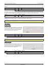
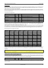
Register Value Direction Description Range
SPC_HIGHLEVEL0 42000 r/w Defines the upper level (triggerlevel) for channel 0 -31 to +31
SPC_HIGHLEVEL1 42001 r/w Defines the upper level (triggerlevel) for channel 1 -31 to +31
SPC_HIGHLEVEL2 42002 r/w Defines the upper level (triggerlevel) for channel 2 -31 to +31
SPC_HIGHLEVEL3 42003 r/w Defines the upper level (triggerlevel) for channel 3 -31 to +31
SPC_LOWLEVEL0 42100 r/w Defines the upper level (triggerlevel) for channel 0 -31 to +31
SPC_LOWLEVEL1 42101 r/w Defines the upper level (triggerlevel) for channel 1 -31 to +31
SPC_LOWLEVEL2 42102 r/w Defines the upper level (triggerlevel) for channel 2 -31 to +31
SPC_LOWLEVEL3 42103 r/w Defines the upper level (triggerlevel) for channel 3 -31 to +31
Input ranges
Triggerlevel ±50 mV ±100 mV ±200 mV ±500 mV ±1 V ±2 V ±5 V
31 +48.4 mV +96.9 mV +193.8 mV +484.4 mV +968.8 mV +1937.5 mV +4843.8 mV
30 +46.9 mV +93.8 mV +187.5 mV +468.8 mV +937.5 mV +1875.0 mV +4687.5 mV
…
16 +25.0 mV +50.0 mV +100.0 mV +250.0 mV +500.0 mV +1000.0 mV +2500.0 mV
…
2 +3.1 mV +6.3 mV +12.5 mV +31.3 mV +62.5 mV +125.0 mV +312.5 mV
1 +1.6 mV +3.1 mV +6.3 mV +15.6 mV +31.3 mV +62.5 mV +156.3 mV
0 0.0 mV 0.0 mV 0.0 mV 0.0 mV 0.0 mV 0.0 mV 0.0 mV
-1 -1.6 mV -3.1 mV -6.3 mV -15.6 mV -31.3 mV -62.5 mV -156.3 mV
-2 -3.1 mV -6.3 mV -12.5 mV -31.3 mV -62.5 mV -125.0 mV -312.5 mV
…
-16 -25.0 mV -50.0 mV -100.0 mV -250.0 mV -500.0 mV -1000.0 mV -2500.0 mV
…
-30 -46.9 mV -93.8 mV -187.5 mV -468.8 mV -937.5 mV -1875.0 mV -4687.5 mV
-31 -48.4 mV -96.9 mV -193.8 mV -484.4 mV -968.8 mV -1937.5 mV -4843.8 mV
Stepsize 1.6 mV 3.1 mV 6.3 mV 15.6 mV 31.3 mV 62.5 mV 156.3 mV
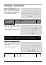
SpcSetParam (hDrv, SPC_TRIGGERMODE , TM_CHANNEL); // Enable channel trigger mode
SpcSetParam (hDrv, SPC_TRIGGERMODE0, TM_CHXPOS ); // Enable channel trigger mode
SpcSetParam (hDrv, SPC_HIGHLEVEL0 , 12 ); // Sets triggerlevel to 75.6 mV
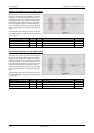
Register Value Direction Description
SPC_READTRGLVLCOUNT 2500 r Contains the number of different possible trigger levels.