


Clock generation Internally generated sample rate
(c) Spectrum GmbH 55
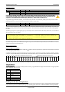
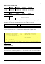
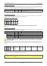
Maximum internal sample rate in MS/s
Using plain quartz with no PLL
In some cases it is useful for the application not to have the on-board PLL activated. Although the PLL used on the Spectrum boards is a low-
jitter version it still produces more clock jitter than a plain quartz oscillator. For these cases the Spectrum boards have the opportunity to switch
off the PLL by software and use a simple clock divider.
The sample rates that could be set are then limited to the quartz speed divided by one of the below mentioned dividers. The quartz used on
the board is similar to the maximum sample rate the board can achieve. As with PLL mode it’s also possible to set a desired sample rate and
read it back. The result will then again be the best matching sample rate.
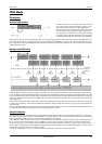
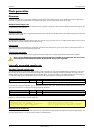
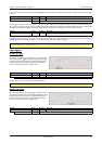
Available divider values
External reference clock
If you have an external clock generator with a extremly stable frequency, you can use it as a reference clock. You can connect it to the external
clock connector and the PLL will be fed with this clock instead of the internal reference. Due to the fact that the driver needs to know the
external fed in frequency for an exact calculation of the sample rate you must set the the SPC_REFERENCECLOCK register accordingly. The
driver automatically sets the PLL to achieve the desired sample rate. Therefore it examines the reference clock and the sample rate registers.
Example of reference clock:
Termination of the clock input
If the external connector is used as an input, either for feeding in an external reference clock or for external clocking you can enable a 50
Ohm termination on the board. If the termination is disabled, the impedance is 1 Megaohm. Please make sure that your source is capable
of driving that current and that it still fulfills the clock input specification as given in the technical data section.
External clocking
Direct external clock
An external clock can be fed in on the external clock connector of the board. This can be any clock, that matches the specification of the
board. The external clock signal can be used to synchronize the board on a system clock or to feed in an exact matching sample rate.
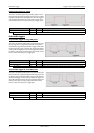
The maximum values for the external clock is board dependant and shown in the table below.
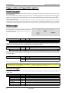
Remapped channels
2020
2021
2030
2031
ch0 ch1 ch2 ch3
x 50 50 200 200
x x 50 50 100 100
x x n.a. 50 n.a. 200
xxxxn.a.50 n.a.100
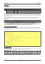
Register Value Direction Description
SPC_PLL_ENABLE 20030 r/w A „1“ enables the PLL mode (default) or disables it by writing a 0 to this register
1 2 4 8 101620405080100200
400 500 800 1000 2000
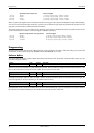
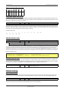
Register Value Direction Description
SPC_REFERENCECLOCK 20140 r/w Programs the external reference clock in the range from 1 MHz to 125 MHz.
0 Internal reference is used for internal sample rate generation.
External sample rate in Hz as an integer value External reference is used. You need to set up this register exactly to the frequency of the external fed in clock.
SpcSetParam (hDrv, SPC_EXTERNALCLOCK, 0); // Set to internal clock
SpcSetParam (hDrv, SPC_REFERENCECLOCK, 10000000); // Reference clock that is fed in is 10 MHz
SpcSetParam (hDrv, SPC_SAMPLERATE, 25000000); // We want to have 25 MHz as sample rate
Register Value Direction Description
SPC_CLOCK50OHM 20120 r/w A „1“ enables the 50 Ohm termination at the external clock connector. Only possible, when using
the external connector as an input.
Register Value Direction Description
SPC_EXTERNALCLOCK 20100 r/w Enables the external clock input. If external clock input is disabled, internal clock will be used.