


SSI
EPS2U Power Supply Design Guide, V2.1
If the optional server signal connector is not used on the power supply or the connector is unplugged, the power
supply shall utilize the 3.3RS on the baseboard connector (Pin 1).
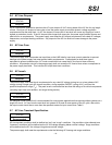
Connector housing: 5-pin Molex 50-57-9405 or equivalent
Contacts: Molex 16-02-0088 or equivalent (gold plated)
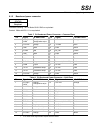
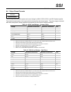
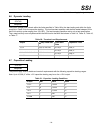
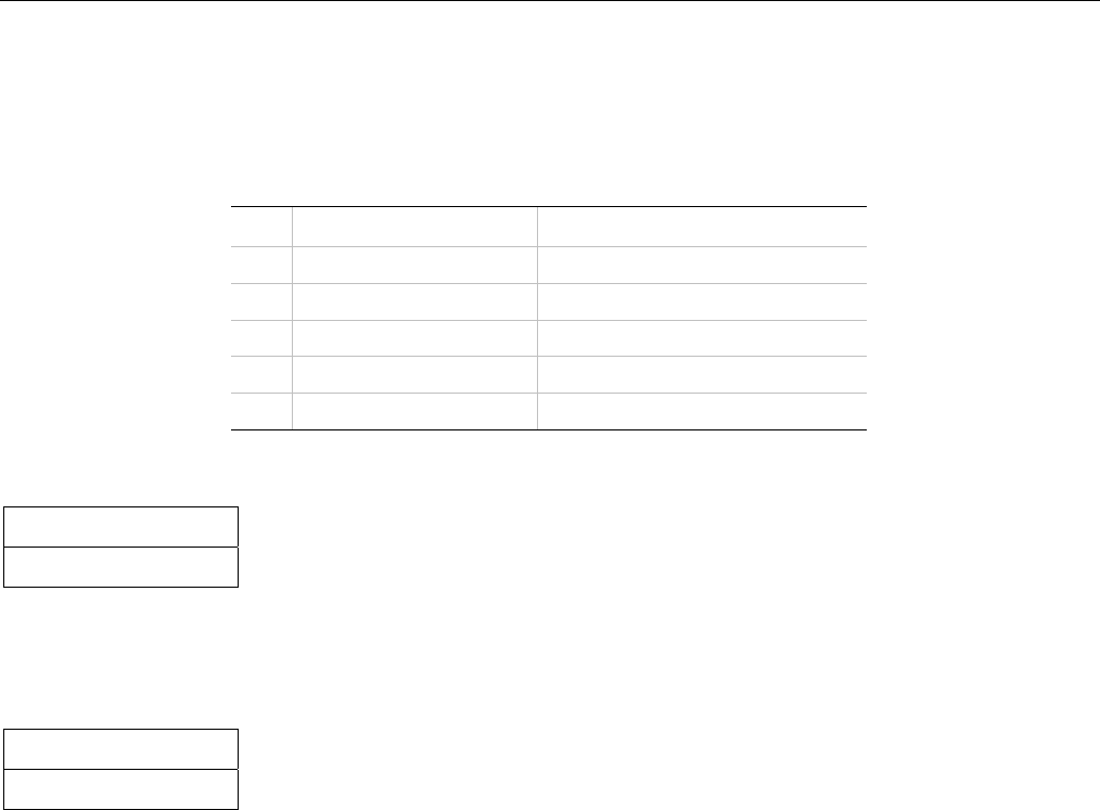
Table 13: Server Signal Connector
Pin Signal 24 AWG Color
1 I2C Clock White/Green Stripe
2 I2C Data White/Yellow Stripe
3 Reserved NA
4 ReturnS Black/White Stripe
5 3.3RS Orange/White Stripe
6.2 Grounding
STATUS
Required
The ground of the pins of the power supply wire harness provides the power return path. The wire harness
ground pins shall be connected to safety ground (power supply enclosure).
6.3 Remote Sense
STATUS
Optional
The power supply may have remote sense for the +3.3V (3.3VS) and return (ReturnS) if the Optional Server
Signal connector is implemented. The remote sense return (ReturnS) is used to regulate out ground drops for all
output voltages; +3.3V, +5 V, +12V1, +12V2, +12V3, -12 V, and 5 VSB. The 3.3V remote sense (3.3VS) is used
to regulate out drops in the system for the +3.3 V output. The remote sense input impedance to the power supply
must be greater than 200 W on 3.3 VS and ReturnS. This is the value of the resistor connecting the remote
sense to the output voltage internal to the power supply. Remote sense must be able to regulate out a minimum
of 200 mV drop on the +3.3 V output. The remote sense return (ReturnS) must be able to regulate out a minimum
of 200 mV drop in the power ground return. The current in any remote sense line shall be less than 5 mA to
prevent voltage sensing errors. The power supply must operate within specification over the full range of voltage
drops from the power supply’s output connector to the remote sense points.
- 16 -