


SSI
EPS2U Power Supply Design Guide, V2.1
7 Protection Circuits
STATUS
Required
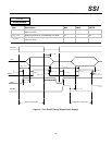
Protection circuits inside the power supply shall cause only the power supply’s main outputs to shutdown. If the
power supply latches off due to a protection circuit tripping, an AC cycle OFF for 15 s and a PSON
#
cycle HIGH
for 1 s must be able to reset the power supply.
7.1 Current Limit
STATUS
Required
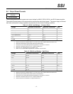
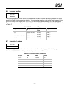
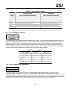
The power supply shall have current limit to prevent the +3.3 V, +5 V, and +12 V outputs from exceeding the
values shown in Table 25. If the current limits are exceeded, the power supply shall shutdown and latch off. The
latch will be cleared by toggling the PSON
#
signal or by an AC power interruption. The power supply shall not be
damaged from repeated power cycling in this condition. -12 V and 5 VSB shall be protected under over current or
shorted conditions so that no damage can occur to the power supply.
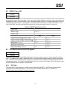
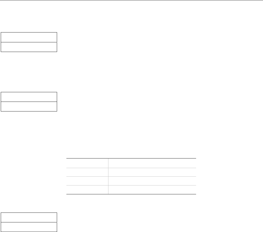
Table 25: Over Current Protection
Voltage Over Current Limit (Iout limit)
+3.3 V 110% minimum; 150% maximum
+5 V 110% minimum; 150% maximum
+12V 110% minimum; 150% maximum
7.2 240VA Protection
STATUS
Recommended
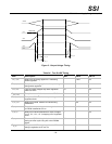
System designs may require user access to energized areas of the system. In these cases the power supply may
be required to meet regulatory 240VA limits for any power rail. Since the +12V rail combined power exceeds
240VA it must be divided into separate channels to meet this requirement. Each separate rail needs to be limited
to less than 20A for each +12V rail. The separate +12V rails do not necessarily need to be independently
regulated outputs. They can share a common power conversion stage. For common plane systems, the +12V rail
is divided into either two or three rails. For split plane systems, the +12V rail is split into four rails. Refer to section
6.4 for how the 12V rail is split between different output connectors.
- 24 -