


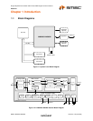

Single-Chip Ethernet Controller with HP Auto-MDIX Support and PCI Interface
Datasheet
Revision 1.22 (09-25-08) 18 SMSC LAN9420/LAN9420i
DATASHEET
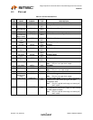
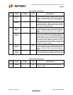
Table 2.3 GPIO and LED Pins
NUM
PINS NAME SYMBOL
BUFFER
TYPE DESCRIPTION
1
General
Purpose I/O
data 0
GPIO0 IS/O12/
OD12
General Purpose I/O data 0: This general-purpose pin is
fully programmable as either push-pull output, open-drain
output or input by writing the GPIO_CFG configuration
register in the SCSR. GPIO pins are Schmitt-triggered
inputs.
nLED1 (Speed
Indicator)
nLED1 OD12 nLED1 (Speed Indicator): This pin can also function as
the Ethernet speed indicator LED and is driven low when
the operating speed is 100Mbs, during auto-negotiation,
and when the cable is disconnected. This pin is driven
high only during 10Mbs operation.
1
General
Purpose I/O
data 1
GPIO1 IS/O12/
OD12
General Purpose I/O data 1: This general-purpose pin is
fully programmable as either push-pull output, open-drain
output or input by writing the GPIO_CFG configuration
register in the SCSR. GPIO pins are Schmitt-triggered
inputs.
nLED2 (Link &
Activity
Indicator)
nLED2 OD12 nLED2 (Link & Activity Indicator): This pin can also
function as the Ethernet Link and Activity Indicator LED
and is driven low (LED on) when LAN9420/LAN9420i
detects a valid link. This pin is pulsed high (LED off) for
80mS whenever transmit or receive activity is detected.
This pin is then driven low again for a minimum of 80mS,
after which time it will repeat the process if TX or RX
activity is detected. Effectively, LED2 is activated solid for
a link. When transmit or receive activity is sensed, LED2
will flash as an activity indicator.
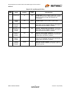
1
General
Purpose I/O
data 2
GPIO2 IS/O12/
OD12
General Purpose I/O data 2: This general-purpose pin is
fully programmable as either push-pull output, open-drain
output or input by writing the GPIO_CFG configuration
register in the SCSR. GPIO pins are Schmitt-triggered
inputs.
nLED3 (Full-
Duplex
Indicator)
nLED3 OD12 nLED3 (Full-Duplex Indicator): This pin can also
function as the Ethernet Full-Duplex Indicator LED and is
driven low when the link is operating in full-duplex mode.
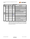
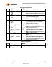
Table 2.4 Configuration Pins
NUM
PINS NAME SYMBOL
BUFFER
TYPE DESCRIPTION
1
AutoMDIX
Enable
AUTOMDIX_EN IS
(PU)
AutoMDIX Enable: Enables Auto-MDIX. Pull high or
leave unconnected to enable Auto-MDIX, pull low to
disable Auto-MDIX.