


Single-Chip Ethernet Controller with HP Auto-MDIX Support and PCI Interface
Datasheet
SMSC LAN9420/LAN9420i 77 Revision 1.22 (09-25-08)
DATASHEET
detection. Refer to section Section 3.7.6, "Detecting Power Management Events," on page 80 for more
information.
3.7.4.3.2 EXITING THE D0
A
STATE
The device will exit the D0
A
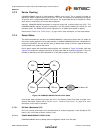
state under the following conditions. State transitions are illustrated in
Figure 3.28 on page 75.
D0
A
to D3
HOT
(T3): This transition occurs when, during normal device operation, the Host system
selects the “D3” state in the Power Management State (PM_STATE) field of the PCI Power
Management Control and Status Register (PCI_PMCSR). (PCInRST=1, PM_STATE=00b to 11b,
VAUXDET=X, PWRGOOD=1). If the PME Enable (PME_EN) bit in the PCI Power Management
Control and Status Register (PCI_PMCSR) is cleared, the internal PHY is reset and is placed in
the General Power-Down mode on this transition. If PME Enable (PME_EN) is set, it is assumed
that the device will be required to detect Ethernet power management events and the PHY is not
reset or placed in General Power-Down mode.
D0
A
to D0
U
(T7): This transition occurs when PCInRST is asserted while in the D0
A
state
(PCInRST=1 to 0, PM_STATE=00b, VAUXDET=X, PWRGOOD=1).
D0
A
to D3
COLD
(T11): This transition occurs when all power supplies are operational and the device
has been initialized and the Power Management State (PM_STATE) field of the PCI Power
Management Control and Status Register (PCI_PMCSR) is set to “D0”, and then PCI power is
turned off and 3.3Vaux is still operational (PCInRST=1, PM_STATE=00b, VAUXDET=1,
PWRGOOD=1 to 0).The internal PHY is reset and is placed in the General Power-Down mode on
this transition. Note that if VAUXDET=0, the device is being powered from the PCI +3.3V supply
and will turn off (G3) when PCI power is removed.
D0
A
to G3 (T12): This transition occurs when all power supplies are turned off (PCInRST=X,
PM_STATE=XXb, VAUXDET=1 to 0, PWRGOOD=1 to 0). For example, total power failure.
3.7.4.4 The D3
HOT
State
In this state the PCI power is on, but normal Ethernet receive and transmit operation is disabled. In
D3
HOT
power is reduced by disabling the internal PLL and derivative clocks. If the PME Enable
(PME_EN) bit in the PCI Power Management Control and Status Register (PCI_PMCSR) is cleared,
power is also conserved by placing the internal PHY into General Power-Down mode on transition to
this state.
In D3
HOT
PCI configuration accesses are permitted, but the device will not respond to PCI memory or
I/O accesses. While in this state, the Power Management State (PM_STATE) field of the PCI Power
Management Control and Status Register (PCI_PMCSR) will indicate a setting of 11b (D3 state).
3.7.4.4.1 POWER MANAGEMENT EVENTS IN D3
HOT
If configured to do so, the device is capable of detecting MAC (WOL, Magic Packet) and PHY (link
status change) wake events and is capable of asserting nPME as a result of detection. Refer to section
Section 3.7.6, "Detecting Power Management Events," on page 80 for more information.
3.7.4.4.2 EXITING THE D3
HOT
STATE
The device will exit the D3
HOT
state under the following conditions. State transitions are illustrated in
Figure 3.28 on page 75.
D3
HOT
to D3
COLD
(T4): This transition occurs after the device has been placed in the D3
HOT
state
by the Host system and then PCI power is turned off, but PCI 3.3Vaux remains operational
(PCInRST=X, PM_STATE=11b, VAUXDET=1, PWRGOOD=1 to 0). In this state the device is
powered by the PCI 3.3Vaux supply.
D3
HOT
to D0
U
(T5): This transition occurs when the device is in the D3
HOT
state and Host system
selects the “D0” state in the Power Management State (PM_STATE) field of the PCI Power
Management Control and Status Register (PCI_PMCSR) (PCInRST=1, PM_STATE=11b to 00b,
VAUXDET=X, PWRGOOD=1). A D3 Transition Reset (D3RST) occurs during this transition. Refer
to Section 3.7.5, "Resets," on page 79 to for more information on this reset.