


Single-Chip Ethernet Controller with HP Auto-MDIX Support and PCI Interface
Datasheet
Revision 1.22 (09-25-08) 20 SMSC LAN9420/LAN9420i
DATASHEET
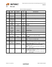
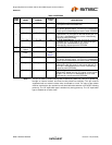
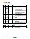
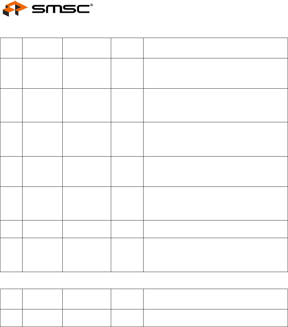
Table 2.6 Power and Ground Pins
NUM
PINS NAME SYMBOL
BUFFER
TYPE DESCRIPTION
2
+3.3V
Analog
Power
Supply
VDD33A P +3.3V Analog Power Supply
Refer to the LAN9420/LAN9420i application note for
connection information.
1
+1.8V PLL
Power
Supply
VDD18PLL P +1.8V PLL Power Supply: This pin must be connected
to VDD18CORE for proper operation.
Refer to the LAN9420/LAN9420i application note for
additional connection information.
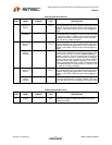
1
+1.8V TX
Power
Supply
VDD18TX P +1.8V Transmitter Power Supply: This pin must be
connected to VDD18CORE for proper operation.
Refer to the LAN9420/LAN9420i application note for
additional connection information.
1
+3.3V
Master Bias
Power
Supply
VDD33BIAS P +3.3V Master Bias Power Supply
Refer to the LAN9420/LAN9420i application note for
additional connection information.
15
+3.3V I/O
Power
VDD33IO P +3.3V Power Supply for I/O Pins and Internal
Regulator
Refer to the LAN9420/LAN9420i application note for
additional connection information.
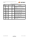
21 Ground VSS P Common Ground for I/O Pins, Core, and Analog
Circuitry
3
+1.8V Core
Power
VDD18CORE P Digital Core +1.8V Power Supply Output from
Internal Regulator
Refer to the LAN9420/LAN9420i application note for
additional connection information.
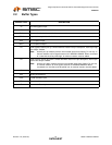
Table 2.7 No-Connect Pins
NUM
PINS NAME SYMBOL
BUFFER
TYPE DESCRIPTION
17 No Connect NC - No Connect: These pins must be left floating for
normal device operation.