


Single-Chip Ethernet Controller with HP Auto-MDIX Support and PCI Interface
Datasheet
Revision 1.22 (09-25-08) 92 SMSC LAN9420/LAN9420i
DATASHEET
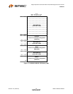
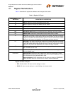
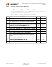
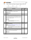
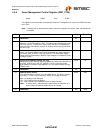
4.2.5 General Purpose Input/Output Configuration Register (GPIO_CFG)
This register configures the GPIO and LED functions.
Offset: 00D0h Size: 32 bits
BITS DESCRIPTION TYPE DEFAULT
31 RESERVED RO -
30:28 LED[3:1] enable (LEDx_EN)
A ’1’ sets the associated pin as an LED output. When cleared low, the pin
functions as a GPIO signal. Bits are assigned as follows:
LED1/GPIO0 - bit 28
LED2/GPIO1 - bit 29
LED3/GPIO2 - bit 30
R/W 000b
27 RESERVED RO -
26:24 GPIO Interrupt Polarity 0-2 (GPIO_INT_POL)
When set high, a high logic level on the corresponding GPIO pin will set
the corresponding INT_STS register bit. When cleared low, a low logic level
on the corresponding GPIO pin will set the corresponding INT_STS register
bit.
GPIO interrupts must also be enabled in GPIOx_INT_EN in the INT_EN
register. Bits are assigned as follows:
GPIO0 - bit 24
GPIO1 - bit 25
GPIO2 - bit 26
Note: GPIO inputs must be active for greater than 80nS to be
recognized as interrupt inputs.
R/W 000b
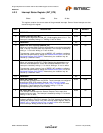
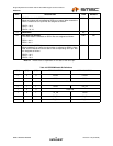
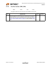
23 RESERVED RO -
22:20 EEPROM Enable (EEPR_EN)
The value of this field determines the function of the external EEDIO and
EECLK.
Please refer to Table 4.3, “EEPROM Enable Bit Definitions,” on page 93 for
the EEPROM Enable bit function definitions.
Note: The Host must not change the function of the EEDIO and EECLK
pins when an EEPROM read or write cycle is in progress. Do not
use reserved setting.
R/W 000b
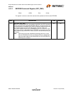
19 RESERVED RO -
18:16 GPIO Buffer Type 0-2 (GPIOBUFn)
When set, the output buffer for the corresponding GPIO signal is configured
as a push/pull driver. When cleared, the corresponding GPIO set configured
as an open-drain driver. Bits are assigned as follows:
GPIO0 – bit 16
GPIO1 – bit 17
GPIO2 – bit 18
R/W 000b
15:11 RESERVED RO -