


Chapter 5: Advanced Motherboard Setup
5-11
5-9 Connector
Definitions
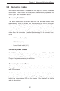
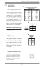
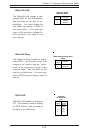
Power Supply Connectors
The primary power supply connector
on the P4SC8 meets the SSI
(Superset ATX) 24-pin specifica-
tion. Refer to the table on the right
for the pin definitions of the ATX
24-pin power connector. You
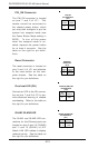
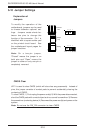
must also connect the 4-pin J21
power connector to your power
supply. Refer to the table below
right for the J21 (12V) connector.
Important: you must connect J21 to
your power supply to meet the ATX
safety requirements.
Pins #
1 & 2
3 & 4
Definition
Ground
+12 V
+12V 4-pin PWR
Connector
(J21)
Required
Connection
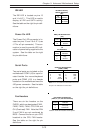
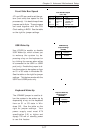
IR Connector
The infrared connector is located
on J16. See the table on the right
for pin definitions. See the Tech-
nical Support section of our web
page for information on the infra-
red devices you can connect to
the system.
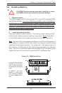
ATX Power Supply 24-pin Connector
Pin Definitions (J20)
Pin Number Definition
13 +3.3V
14 -12V
15 COM
16 PS_ON#
17 COM
18 COM
19 COM
20 Res(NC)
21 +5V
22 +5V
23 +5V
24 COM
Pin Number Definition
1 +3.3V
2 +3.3V
3 COM
4 +5V
5 COM
6 +5V
7 COM
8 PWR_OK
9 5VSB
10 +12V
11 +12V
12 +3.3V
Pin
Number
1
2
3
4
5
6
Definition
+5V
CIRRX
IRRX
Ground
IRTX
NC
Infrared Pin
Definitions
(J16)
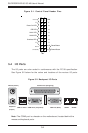
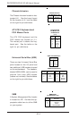
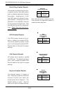
GLAN1/2 (Ethernet Ports)
Two Ethernet ports (designated
GLAN1 and GLAN2) are located
beside the VGA port on the I/O
backplane. These ports accept
RJ45 type cables.