


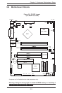
Chapter 5: Advanced Motherboard Setup
5-13
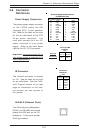
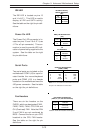
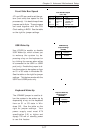
Serial Ports
Two serial ports are included on the
motherboard: COM1 (J9) is a port lo-
cated beside the mouse/keyboard
ports and COM2 (J10) is a header
located on the motherboard near the
J20 power connector. See the table
on the right for pin definitions.
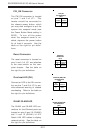
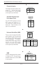
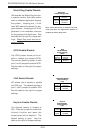
Power On LED
The Power On LED connector is lo-
cated on pins 15 and 16 of JF1 (use
J17 for a 3-pin connector). This con-
nection is used to provide LED indi-
cation of power being supplied to the
system. See the table on the right
for pin definitions.
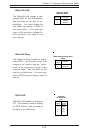
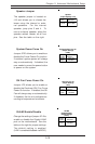
IDE LED
The IDE LED is located on pins 13
and 14 of JF1. This LED is used to
display all IDE and SATA activity.
See the table on the right for pin defi-
nitions.
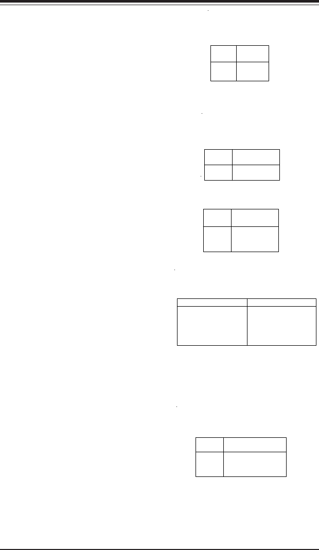
Hard Drive Activity
LED Pin Definitions
(JF1)
Pin
Number
13
14
Definition
+5V
HD Activity
Pin
Number
15
16
Definition
+5V
Ground
PWR_LED Pin Definitions
(JF1)
Serial Port Pin Definitions
(COM1, COM2)
Pin Number Definition
1 CD
2 RD
3 TD
4 DTR
5 Ground
Pin Number Definition
6 DSR
7 RTS
8 CTS
9 RI
10 NC
Note: Pin 10 is included on the header but not on
the port. NC indicates no connection.
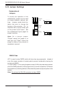
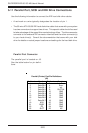
Fan Headers
There are six fan headers on the
P4SC8, which are designated FAN1,
FAN2, FAN3, FAN4, CPU FAN and
OH (Overheat) FAN. Note that FAN
3 and FAN 4 are not monitored by
BIOS. Connect the fan on your CPU
heatsink to the CPU FAN header.
See the table on the right for pin
definitions.
Fan Header Pin Definitions
(FAN1, 2, 3, 4, CPU and Overheat)
Pin
Number
1
2
3
Definition
Ground (black)
+12V (red)
Tachometer
Caution: These fan headers are DC power.
Pin
Number
1
2
3
Definition
+5V
Key
Ground
J17
Pin Definitions