


5-14
SUPERSERVER 5013C-M8 User's Manual
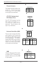
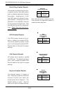
PS/2 Keyboard
and Mouse Port
Pin Definitions
(J11)
Pin
Number
1
2
3
4
5
6
Definition
Data
NC
Ground
VCC
Clock
NC
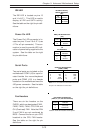
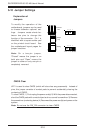
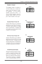
Chassis Intrusion
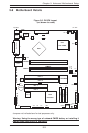
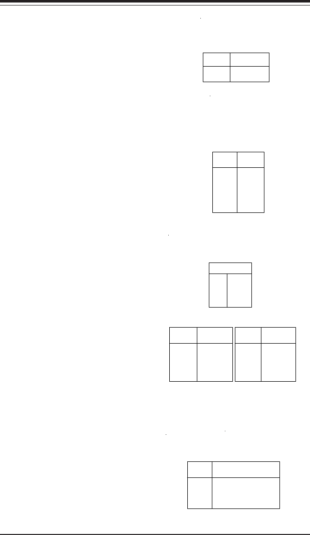
The Chassis Intrusion header is des-
ignated JL1. See the board layout
for the location of JL1 and the table
on the right for pin definitions.
Pin
Number
1
2
Definition
Intrusion Input
Ground
Chassis Intrusion
Pin Definitions (JL1)
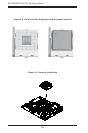
ATX PS/2 Keyboard and
PS/2 Mouse Ports
The ATX PS/2 keyboard and the
PS/2 mouse are located on J11.
The mouse port is above the key-
board port. See the table on the
right for pin definitions.
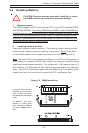
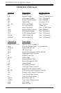
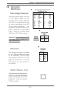
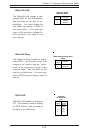
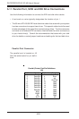
Universal Serial Bus (USB)
There are two Universal Serial Bus
ports located on the I/O panel and
two additional USB headers located
on the motherboard. The headers,
labeled USB3/USB4, can be used to
provide front side USB access
(cables not included). See the tables
on the right for pin definitions.
Pin# Definition
1 +5V
2 P0-
3 P0+
4 Ground
Pin
Number
2
4
6
8
10
Definition
+5V
PO-
PO+
Ground
Ground
Pin
Number
1
3
5
7
Definition
+5V
PO-
PO+
Ground
USB1/2 Pin Definitions
USB3/4 Pin Definitions
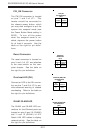
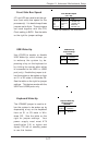
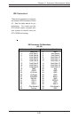
SMB
A System Management Bus header
is located at J25. Connect the ap-
propriate cable here to utilize SMB
on your system.
SMB Header
Pin Definitions (J15)
Pin
Number
1
2
3
4
Definition
Data
Ground
Clock
No Connection