


5-20
SUPERSERVER 5013C-M8 User's Manual
5-11 Parallel Port, SCSI and IDE Drive Connections
Use the following information to connect the IDE hard disk drive cables.
• A red mark on a wire typically designates the location of pin 1.
• The 80-wire ATA100/66 IDE hard disk drive cable that came with your system
has two connectors to support two drives. This special cable should be used
to take advantage of the speed this new technology offers. The blue connector
connects to the onboard IDE connector interface and the other connector(s)
to your hard drive(s). Consult the documentation that came with your disk
drive for details on actual jumper locations and settings for the hard disk drive.
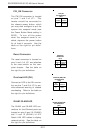
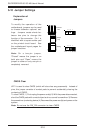
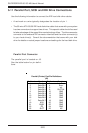
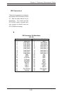
Parallel Port Connector
The parallel port is located on J8.
See the table below for pin defini-
tions.
Pin Number Function
1 Strobe-
3 Data Bit 0
5 Data Bit 1
7 Data Bit 2
9 Data Bit 3
11 Data Bit 4
13 Data Bit 5
15 Data Bit 6
17 Data Bit 7
19 ACK
21 BUSY
23 PE
25 SLCT
Pin Number Function
2 Auto Feed-
4 Error-
6 Init-
8 SLCT IN-
10 GND
12 GND
14 GND
16 GND
18 GND
20 GND
22 GND
24 GND
26 NC
Parallel (Printer) Port Pin Definitions
(J8)