


5-12
SUPERSERVER 5013C-M8 User's Manual
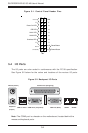
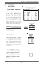
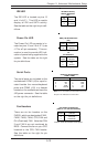
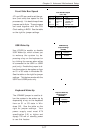
Reset Connector
The reset connector is located on
pins 3 and 4 of JF1 and attaches
to the reset switch on the com-
puter chassis. See the table on
the right for pin definitions.
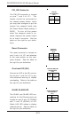
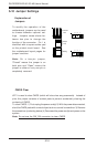
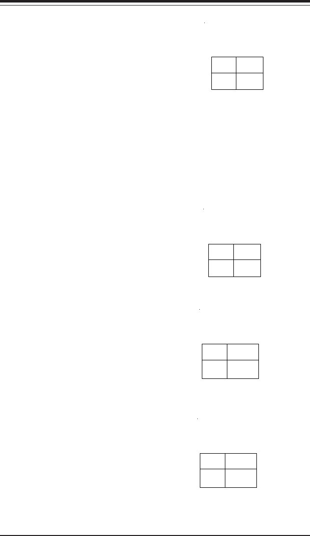
PW_ON Connector
The PW_ON connector is located
on pins 1 and 2 of JF1. This
header should be connected to
the chassis power button, which
you may also configure to put the
system into suspend mode (see
the Power Button Mode setting in
BIOS). To turn off the power
when the suspend mode is en-
abled, depress the power button
for at least 4 seconds. See the
table on the right for pin defini-
tions.
Pin
Number
1
2
Definition
Signal
+3V Stby
PW_ON
Pin Definitions
(JF1)
Pin
Number
3
4
Definition
Reset
Ground
Reset Pin
Definitions
(JF1)
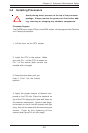
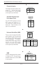
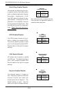
Overheat LED (OH)
Connect an LED to the OH connec-
tion on pins 7 and 8 of JF1 to pro-
vide advanced warning of chassis
overheating. Refer to the table on
the right for pin definitions.
Overheat (OH) LED
Pin Definitions
(JF1)
Pin
Number
7
8
Definition
Vcc
GND
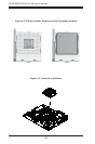
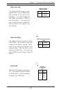
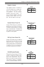
GLAN1/GLAN2 LED
The GLAN1 and GLAN2 LED con-
nections for the Ethernet ports are
located on pins 9 and 10 (GLAN2)
and 11 and 12 (GLAN1) of JF2.
Attach LAN LED cables to display
network activity. See the table on
the right for pin definitions.
GLAN1/GLAN2 LED
Pin Definitions
(JF1)
Pin
Number
9,10
11,12
Definition
Vcc
GND